This thread has been locked.

If you have a related question, please click the "Ask a related question" button in the top right corner. The newly created question will be automatically linked to this question.

SN6501: Drive two transformer in parallel

Part Number: SN6501

Hi Team,

I have a further doubt on this topic, hope you could be so kind to resolve it.

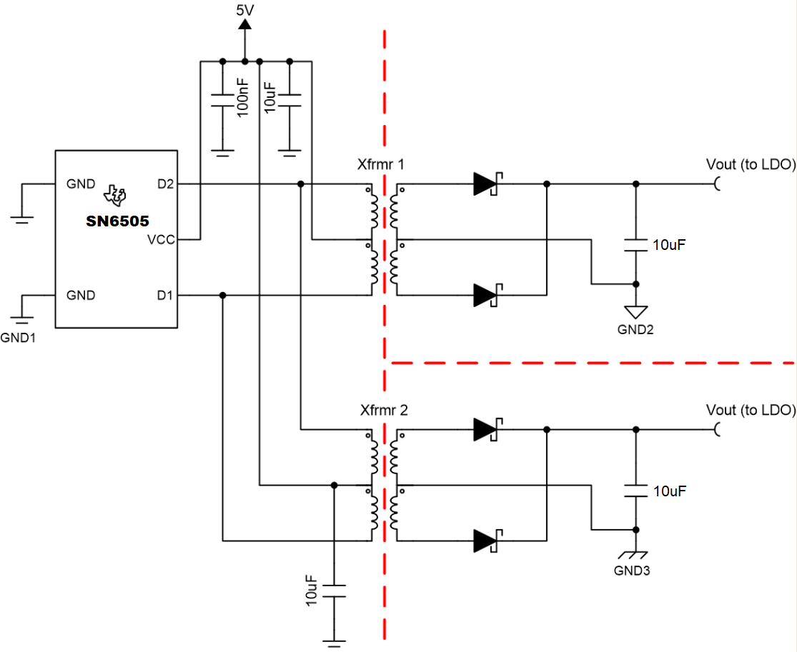
I have understood that when there is a small imbalance in the push-pull transformer primary windings or in traces impedance, the resistance of the output switch sinking higher power will increase and the balance is restored.

What happens if one of the two transformer in parallel (T1) has the two primary perfectly matched but the other (T2) has a mismatch? Does the RDS positive temperature coefficient of the switches creates an imbalance in the flux of the transformer T1 which has the two primary perfectly matched?

Is there a minimum matching requirement on windings to be requested to the Transformer manufacturer?

Thanks in advance for what you can answer.

Best regards
Alberto

  • Hi Alberto,

    Thank you for posting to E2E!

    Yes, your understanding of the output switches heating up to correct small flux imbalances is correct. If two transformers are connected to the switching pins of SN6501, the sum of the currents through each transformer will heat D1 or D2 FETs accordingly, meaning that if one transformer has a small imbalance, the output FET connected to this 1/2 of the transformer and the 1/2 of the transformer in parallel will heat up, reducing the voltage slightly across both transformers. This would repeat on the other output FET until a new balance point is found for both transformers to operate.

    The timing requirement we identify for transformers used with SN650x devices is V-t product. So long as transformers meet the V-t product requirement for SN6501 (>9.1V-us for 5V applications), we do not expect issues due to switching, even when transformers are connected in parallel. Please do thoroughly test your system and let us know of any additional questions you have.


    Thank you,
    Manuel Chavez

  • Hi Manuel,

    Thanks for your fast feedback!

    My concern is how much mismatch between the two primary winding can be handled by this "RDS heating control", so it can be asked to the manufacturer of the transformer to guarantee it. On the datasheet of the transformers there is only the Vt product but there are no specification on how matched the primary are. Why is this not a problem? maybe a 10% of difference in primary inductance values is handled by the converter or 10% difference is it impossible (too much) for the transformer construction? 

    Measuring current into pin 2 of the Tras. I see different Imax value when Q1 or Q2 are on, is this due to the different impedance of the two primary windigns-connections? how shall I evaluate this is okay or it is too much?

    You also say this effect can correct smal flux imbalances, there are no other control in the converter like current or voltage mode, in order to avoid flux walking?  

    Thank you for the support, I have no experience with push-pull converter.

    Best regards,

    Alberto

  • Hi Alberto,

    You're welcome! Transformers are usually manufactured to closely balance the transformer 1/2 windings and guarantee all parameters in their datasheets. Although the numbers vary from transformer manufacturer-to-manufacturer and even part-to-part, a 10% difference seems too big.

    Which current values are you seeing when Q1 is on vs. when Q2 is on? Which transformer part number is being used? If possible, please share a schematic of your system for evaluation -- feel free to send me a Request to Connect in case you would not like to post the schematic on this thread.

    Our SN6501 does not have any features to prevent or protect against large flux imbalances while our SN6505 devices feature short-circuit protection and thermal shutdown to protect themselves from damage if flux imbalances become so great that the transformer saturates, and its EN pin can be toggled LOW to power off the IC in such a case, stopping any switching in the transformer.

    Please let me know of any follow-up questions you have, and I look forward to your information as requested above.


    Thank you,
    Manuel Chavez

  • Hi Alberto,

    Thank you for following up with me directly and sharing your schematic as well as voltage and current waveforms.

    From our conversation, although connecting both transformers in this system is causing voltage and current waveforms to look asymmetrical at the transformer pins, the Rds-on temp-rise does compensate for combined imbalances in T1 and T2 when they are connected.

    We encourage you to test this system across expected load current and temperature conditions to ensure reliable operation with margin. If the transformer does not saturate within seconds, it shouldn't saturate under the respective conditions.

    Please feel free to post a new or related question using the red and yellow buttons in the upper right corner of this window to continue this conversation if needed.


    Thank you!
    Manuel Chavez