This thread has been locked.

If you have a related question, please click the "Ask a related question" button in the top right corner. The newly created question will be automatically linked to this question.

SN74V215 FIFO

Other Parts Discussed in Thread: SN74V215

In the FIFO SN74V215, the 18 input data lines are connected to a data source and the clock supply is connected to WCLK and #WEN(active low) is by default tied to ground, so that it is ready at the first instance itself to take the input inside the FIFO.

Consider the case that the setup is initially OFF. At an instance, both the data source and the FIFO are turned ON, but the data source has not produced any output for some clock ticks (just the source and FIFO are connected and turned ON and the CLOCK is running without any data).

What will be recorded inside the FIFO if this is the case? Will there be some junk inside? I don't want any data to be written inside the FIFO until the data source has produced the Data. What should I do?

  • Raju,

    If the FIFO is given proper signals to write data, then it will.  If the data is not valid, then you will capture invalid data.

    A couple concerns from your description.

    Are you applying reset (RS) after power up?  This is required to have stable operation.

    Typically when a system powers up a reset signal (or possibly a power good) will be set/released.   This insures that the system is ready to operate. 

    It is difficult to make more comments on your setup with minimal data.

    Regards,

    Wade

  • Dear Wade,

    Thank you for the reply. I will explain the set up that is intended to develop. 

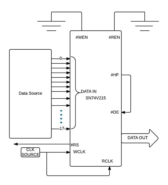
    This is the expected setup. There are two operations: Write and Read.

    Write Operation:

    The data IN of the FIFO is connected to a source. A clock Source provides for both the WCLK and RCLK. The #WEN is tied to ground by default with the expectation that the data will be written directly inside the FIFO.The Reset is purposefully left unconnected here in this setup. Initially the Setup is OFF and as soon as it is turned ON, the data source takes some time to provide the data, but the write clock will be ticking. The FIFO should be in the Reset state since the power up until the valid data has been produced from the source. How to establish this in the FIFO?

    Read Operation:

    The RCLK will also be ticking and the #REN will be tied to ground by default. As soon as the Half full flag is asserted, it produces the LOW signal to make the #OE LOW. Once the #OE is low, then the data inside the FIFO will be sent out. Is there any thing faulty with this setup of Read operation? 

  • Santhosh,

    I have 2 concerns with your setup.

    1) you must assert reset (RS) as described in datasheet for reliable operation.

    2) I don't believe OE will inhibit read FIFO pointers from being used.  You would need to use REN with HF flag to have the FIFO buffer up 1/2 depth before reading from FIFO.

    You will need to make sure that the setup and hold times are met on the assertion of REN using the HF flag.  This is depend on your clock frequency.   It may be a good idea to put flip flop on HF to REN, to add a delay to keep the FIFO over half full and not off/on half full.

    The other issue this will pose is that one your data is done, the HF flag will go back high and you will no longer output the last 1/2 of the data.

    You possibly can work up some logic to handle the REN using HF and empty flags to resolve this.

    Regards,

    Wade

  • Wade,

    Yes, the usage of #REN with the #HF will be more appropriate. And it is also a good idea to add a flip-flop logic in between the #REN and #HF so as to ensure that the data is always more than HF.

    There will be continuous flow of data inside the FIFO(back pressure), which ensures that the data is always more than the HF level.

    Regarding the Reset, it is mentioned in the data sheet  of SN74V215, that the minimum pulse duration for the reset (tRS) should be 10ns. I would be making a delay circuitry which provides the low pulse for reset for at least 10 ns.

    Now, given the same above setup with all the set up and hold times matched, along with this minimum of 10ns reset delay after the power up, will the data be written inside the FIFO at the next moment as soon as the Reset goes HIGH?

    There is something that is mentioned as tRSR (Reset Recovery time) as 8ns(min). What does this mean? The max time up to which this  can extend is also not provided in the data sheet.

    Also what is tRSS(Reset setup time), which is 8ns (min)?