This thread has been locked.

If you have a related question, please click the "Ask a related question" button in the top right corner. The newly created question will be automatically linked to this question.

TPS50601-SP: Master-Slave Mode performed right or not and Purpose of Schottky Diodes in EVAL Board.

Part Number: TPS50601-SP

Hi All,

We are using TPS50601-SP in Master-Slave Mode.

Vin=5v , Vout=1V , Iout= 6A

For this we are following below steps:-TPS50601-PARALLEL.pdf

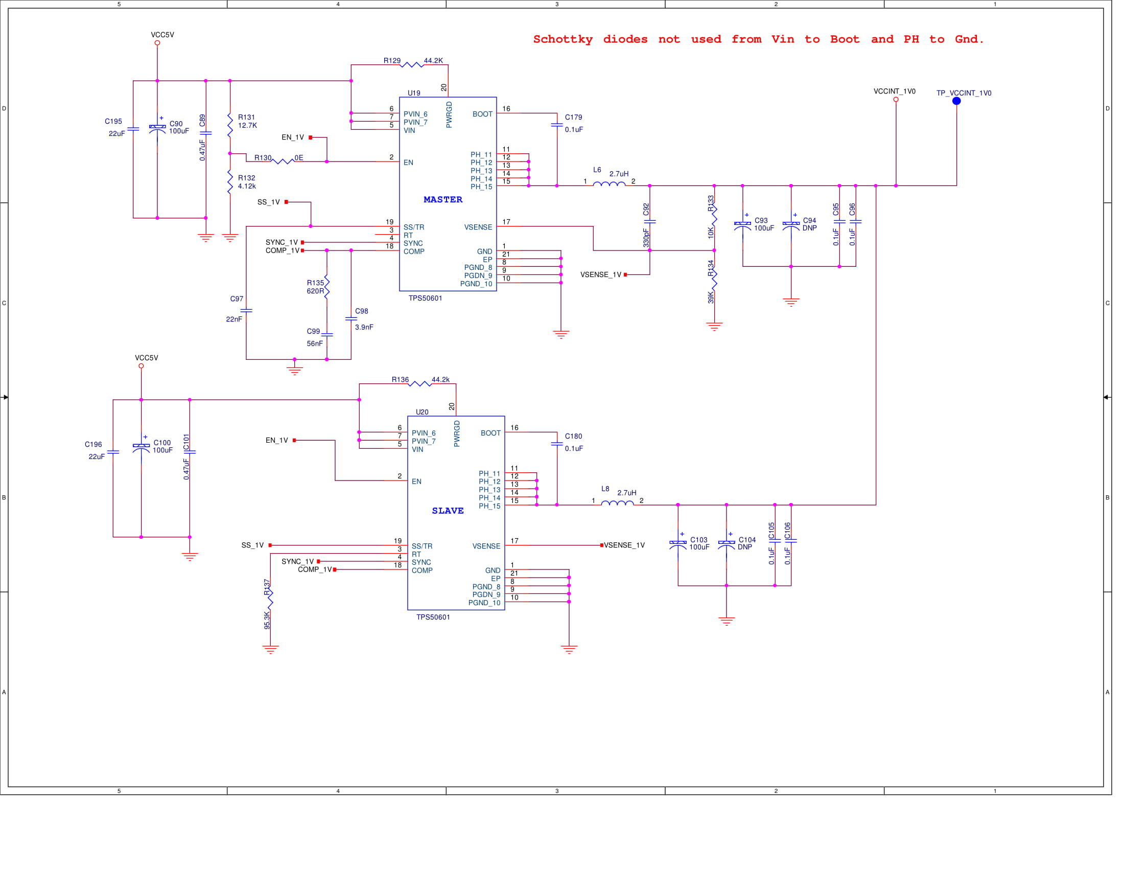
  1. The RT pin of the master device is left floating.
  2. The RT pin on slave device is connected to a 95.3k resistor so that the frequency of the slave device is 500kHz.
  3. Only a single feedback network is connected to the VSENSE pin of the master device. No resistor divider is connected to slave VSENSE pin. Although both VSENSE pins are shorted.
  4. SYNC pin of the master is connected to the SYNC pin of the slave device.
  5. Only a single compensation network is connected to the COMP pin of the master device. Both COMP pins are shorted.
  6. Only a single soft start capacitor is connected to the SS pin of the master device Both SS pins are shorted.
  7. Only a single enable resistor divider is connected to the EN pin of the master device. Both EN pins are shorted.
  8. Master device controls the compensation, soft start and enable networks, the factor of 2 is taken into account when calculating the components associated with these pins.

These points are from application note "TPS54620 Parallel Operation".

Are these steps right or do we need to use separate feedback divider for output at both TPS50601-SP and same for COMP,EN etc and then shorted these pins.

Also in EVAL board of TPS50601-SP Schottky diodes are used from Vin to Boot and PH to Gnd. Are schottky diodes compulsory or we can ignore them?

Attached is the schematic please review it and share your comments.

Early response will be highly appreciated.

Thanks

  • Hi Lalit, your implementation of master/slave operation is correct. The TPS50601A-SP datasheet lists the same steps as the 2 devices are very similar. The reason for the diodes in the TPS50601-SP EVM are:

    1. VIN to BOOT - this is only needed for low VIN applications. It is there to make sure the BOOT domain operates properly under those conditions. It is certainly not needed at VIN=5V.

    2. PH to GND - this is a good practice with switching regulators to provide extra protection for the FETs. As the TPS50601-SP has a max. recommended operating condition of 6.3 V (opposed to 7V in the TPS50601A-SP), I would recommend you keep this diode in place.

    Thanks,

    JV
  • Hi Javier,
    Thanks for a quick reply.
    I have a one more question. In eval board diode used is B230-13-F which has current rating of 2A. Actually, we are already using a schottky diode MELF package in our design for other purpose which has current rating of 1A.
    Can we use the same diode with 1A current rating for connecting it to PH of TPS50601 to gnd?

    As mentioned before Iout is 6A at 1V.
    Thanks

  • Hey Lalit,

    The current rating of the diode is based on the parasitics of the layout.
    If you use a 1A current rated part it is likely fine, but it would need to be confirmed during test.

    Thanks,
    Daniel