This thread has been locked.

If you have a related question, please click the "Ask a related question" button in the top right corner. The newly created question will be automatically linked to this question.

LSF0102: Output Voltage

Part Number: LSF0102
Other Parts Discussed in Thread: SN74LVC2T45

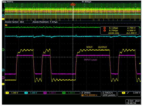
team, there is a question about the UART (8Mbps) application with LSF0102 from 3.3V to 5.0V translator. We found the output voltage having a voltage drop of 0.6V-0.7V when low state. is this behavior normally? if not so, how to solve this problem?

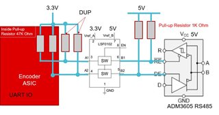
Please also find the block diagram as attached file. Please check if the pull-up resistor needs to be changed or not?

0160.LSF0102.pdf

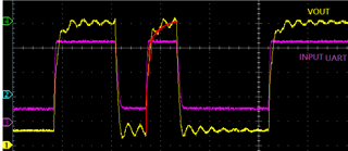
Below waveform is using LSF0102 without Pull-up resistor:


  • The LSF is a passive switch; the UART has to sink the current through all pull-up resistors. I guess that the UART does not have strong output drivers.

    Increasing R12/R18 will make the rising edges slower, and reduce the current and thus the low-level voltage.

    (Please note that you do not need R13/R14 because those I/Os are connected to push/pull outputs.)

    You do not need an auto-bidirectional translator for unidirectional signals. Consider using the SN74LVC2T45 instead.

  • Thanks.

    Here i also updated some information. On the left side of the ASIC, there are 47KOhm pull up resistor. and the external pull-up is now DUP. 

    1. Could you suggest resistor value of the R12/R18?

    2. Since customer has done the layout with LSF0102, they would like to keep this solution on the board. If unidirectional signals as UART is being used, there is no problem right?

    3. Did you mean "UART does not have strong output driver", do you mean the ASIC IC or RS485 IC in the block?

    Regards

    Brian W

  • Hey Brian,

    From the provided image, it looks like there shouldn't be an issue with operation the way the signals are now -- the VOL is about 0.6V, which is plenty low for a 5V input, and the VOH is reaching about 5V with every pulse - which means that the resistors selected are about the right size. My initial recommendation would be to leave the circuit as it is if it's working properly.

    *

    To respond to your questions directly:

    1. Could you suggest resistor value of the R12/R18?

    It looks to me like the current resistor value is what is required to provide good signal integrity for the system:

    You can see in this image that the rise time of the RC is just barely enough to get the signal up to 5V by the end of the shortest pulse.

    You could increase the resistance some (maybe up to 2x), but I wouldn't recommend to do too much.  The driver just may not be strong enough to handle this speed of operation with the LSF.

    The more critical design issue is to ensure that the distance between the LSF device and the 5V IC is as short as possible to reduce parasitic capacitance. Keeping that value small will allow for smaller resistance and faster operation.

    2. Since customer has done the layout with LSF0102, they would like to keep this solution on the board. If unidirectional signals as UART is being used, there is no problem right?

    Since the layout is already complete, there may not be a way to make this work any better other than slowing down the signal clock rate and increasing the pull-up resistor values.

    3. Did you mean "UART does not have strong output driver", do you mean the ASIC IC or RS485 IC in the block?

    He means that the device that is driving the input to the LSF has a relatively high resistance.  This means that sinking current will cause a larger voltage drop than what you would see with a stronger driver (less resistance), and thus your V_OL is higher than what is desirable.