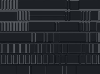
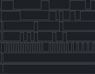
Hi team,
Thank you very much for your help.
Best regards,
This thread has been locked.
If you have a related question, please click the "Ask a related question" button in the top right corner. The newly created question will be automatically linked to this question.
Hi team,
Thank you very much for your help.
Best regards,
Hello,
I'm afraid I don't understand the issue.
Can you provide a schematic of your design and scope shots showing the issue?
If you can't get a scope shot, any diagram showing the timing and signals would be helpful to explain the issue.
What do you mean by "fluctuates betwen shifted and right states each RCLK"?
Hi Maier,
Thank you for your help.
That's Qa-Qh diagram, with wrong outcome.
That's set up with correct one.
The input is about the same (some timings are different and the boards).
RCLK is only one 0-1, but there are two Qn after 7 bit and 8 bit.1-sr row Qh.
Best regards,
Can you please tell us which input and output signals you have captured in these images?
Hi team,
1-st row Qh pin 7
2 - Qg pin 6
3 - Qf
4 - Qe
5 - Qd
6 - Qc
7 - Qb pin 1
8 - RCLK pin 12
Thanks.
Best regards,
These images have only 7 rows.
It would be helpful to see RCLK, SRCLK, and SER.
And I suspect that the setup/hold times are being violated; please zoom in far enough so that these can be checked.
Hi Clemens,
Thank you for you help.
The latest diagram has 8 signals, the bottom one is RCLK. Timings are in uS, the min SER 0-0 is 1 uS, 1-1 more than 10 uS. My question was about the reason of storing data while RCLK is high or 1, so it stored data twice, when RCLK 1-1 and 0-1, not only on rising edge front or 0-1.
SRCLK 0-0 min is 1 us, 1-1 more than 10 uS.
RCLK 0-0 is about 250 us
Vcc is about 4.9V
Best regards,
The outputs can change only at a rising edge of RCLK. It's possible that there is noise in your circuit. Please show an oscilloscope trace of RCLK (at the time when the outputs change wrongly).
Is this a PCB, or some breadboard with many cables? Are there decoupling capacitors? Can you show a schematic?
Hi Clemens,
Thank you for you time.
I can't register noice (may try later, not sure yetif I'm able to do that). PCB for Qh-Qb is simple direct output for LCD. RCLK has an RC itegrator.
The RCLK has no noice I can register (more than 0.1 uS)
RC integrator were tested with C 7000 pF and R 20 K and 10 K.
Polyster film capacitor was used.
Decoupling capacitor 0.1 uF has been used, should I add/change it for 10 nF? LCD consumes 0.7 mA, might it be a problem?
Plus LCD lighting is about 40 mA.
Best regards,
Hello,
It's my understanding that you have an RC filter at the clock input to the device. This can cause errors.
Please see this FAQ: How does a slow or floating input affect a CMOS device?
Hi team,
I need some time to check the trace of RCLK.
BTW: Can the use of 74HCT improve functioning in my case?
Best regards,
HCS (with Schmitt-trigger inputs) would be a better choice.
But you should remove the actual source of problem.
Hi team,
Sorry, cannot send you the trace, didn't have a chance to get it.
Is there any other suggestions?
Best regards,
Hello,
I'm not sure what update you are requesting. We are not working on this issue, as you have not given any further details.