This thread has been locked.

If you have a related question, please click the "Ask a related question" button in the top right corner. The newly created question will be automatically linked to this question.

TXS0104E: TXS0104E level translator is not working

Part Number: TXS0104E

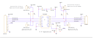
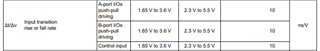
We are using the TXS0104EDR for voltage translation of SPI signal

VCCA side we are supplying 3.3V and VCCB side we are using 5V  ,Below is the schematics reference .

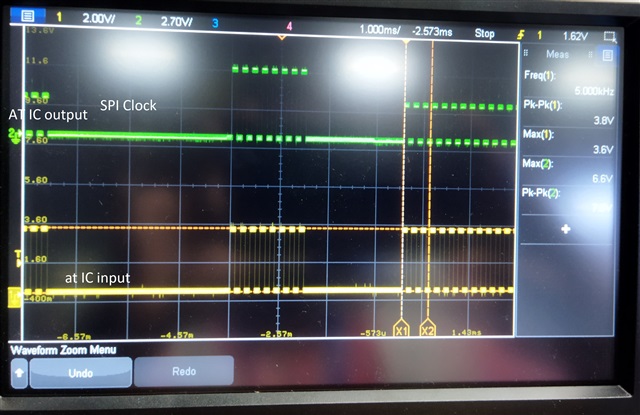
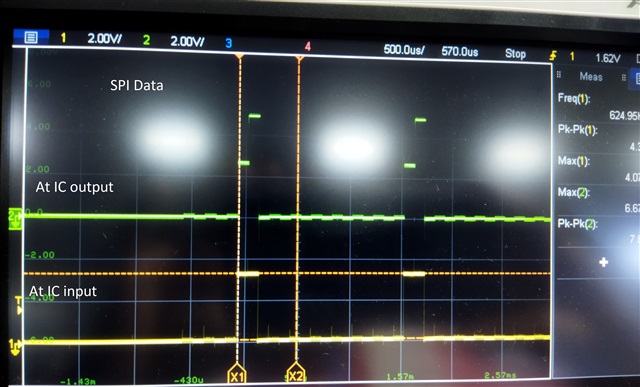
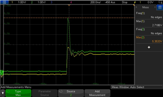
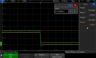
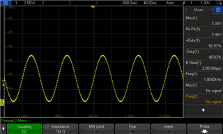
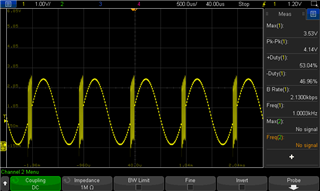
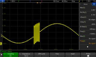
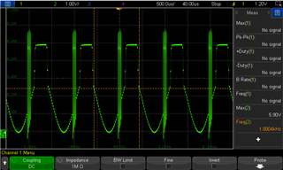
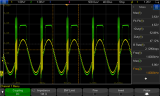
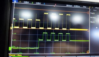
SCK and SDO output signal of SPI at the pin 13 and pin 12 of the IC (U1) is not as expected , we didn’t get the translated output , I have attached the waveform image for the same.

Kindly suggest to solve this issue

  • Please note that the TXS has internal pull-up resistors; you can drop R2/R4/R6/R7.

    Are there any pull-down resistors?

    For signal voltages below VCCA, the TXS works like an analog switch. I guess this is what happens with the green waveform.

    Can you show the input and output signals at the same time?

  • our circuit can be used for SPI / I2C voltage translation .

    we are not using this pullup for SPI configuration , 

    for I2C only we will use this pull ups , as per your suggestion , we will remove those pullups as well 

    here with i have attached separate waveform for SPI data/clock  input and output waveform SPI clock input SPI data input and output waveform

    in the attached waveform , IC output at somepoint seems to be 5V and 3.3V , Similar for both the waveform . 

    kindly suggest a solution for the same 

  • Very strange. The output voltage should always follow the power supply rails.

    Please check that VCCB is actually 5 V, and that there are not any soldering problems with it.

  • Hello,

    TXS0104E should work for this application and external pullups should not necessarily cause an issue. 

    If the line is not getting pulled all the way up, it would suggest that there is some other loading on the line, which is not allowing the pullup to pull the line high.

    Are you sure there is not some other source of bus contention here?

    Michael

  • Hi Michael,

    I have removed the external resistors. Now there are only two decaps (0.1uF/16V), one pull-up resistor (10K) for OE (pin#8). A square wave input was given from function generator, but there is no proper voltage level translation. Also I could see spikes in the output waveform. Please see the waveforms attached. The yellow color waveform is input and green color is output.

    Any suggestions please.

  • There is no proper voltage level translation because the input does not have proper voltage levels. The input signal must go near 3.3 V.

  • Thanks Clemens.

    Input voltage level increased to 3.3V, now I am getting voltage level translation to 5V. But I am facing another issue. If I connected my input source to the level translator board noise is adding up. Any idea why this is happening? Please see the attached waveforms.

    Input source before connecting to the level translator board

    Input source after connecting to the level translator board

    Noise in the Input source after connecting to the level translator board (zoomed image of noise area)

    Output of level translator

    Combined waveform - both input and output

  • Hey Noel,

    This is a digital device and you really shouldn't be applying a sine wave to the input. It should be a square wave with fast transitions. You are violating this spec:

    Doing so can lead to oscillations which is what you are seeing (this isn't noise).

  • Hi Dylan,

    Thanks a lot for pointing out that information.

    I have checked with a square wave as input, that is working fine.

    Thank you.