A related question is a question created from another question. When the related question is created, it will be automatically linked to the original question.
If you have a related question, please click the "Ask a related question" button in the top right corner. The newly created question will be automatically linked to this question.
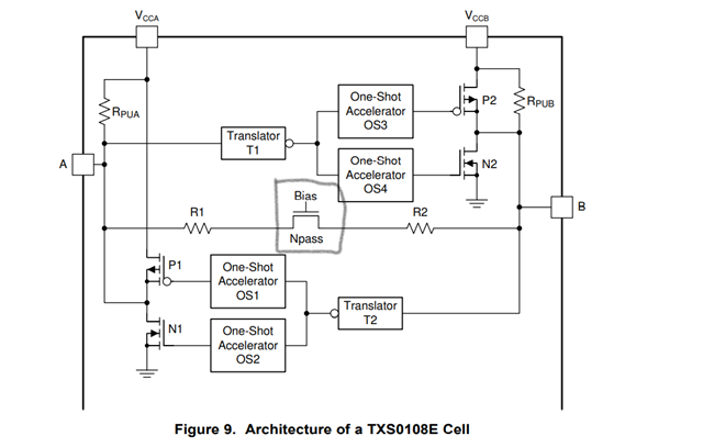
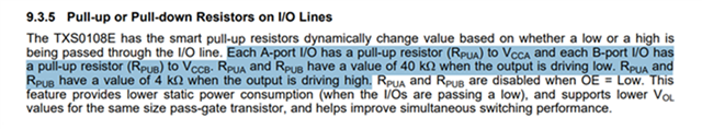
another question. As for the description of pull-up resistance in the datasheet, I would like to ask how the pull-up resistance value switch is realized internally. Is the switch realized after the high and low level is stabilized?
The same circuitry that controls the one-shot circuits also controls the resistor values. Note that when a state change is detected, the one-shots will fire, essentially shorting the I/O pins either high or low for a short time.
So, when transitioning from low to high, the resistors will change to 4kohm and the positive one-shots will fire, shorting the I/O pins to VCCx. When transitioning from high to low, the resistors will change to 40kohm and the negative one-shots will fire, shorting the I/O pins to GND.