This thread has been locked.

If you have a related question, please click the "Ask a related question" button in the top right corner. The newly created question will be automatically linked to this question.

TXS0108E: UART Transmission Issue

Part Number: TXS0108E
Other Parts Discussed in Thread: SN74CB3Q3245, SN74AHC4066

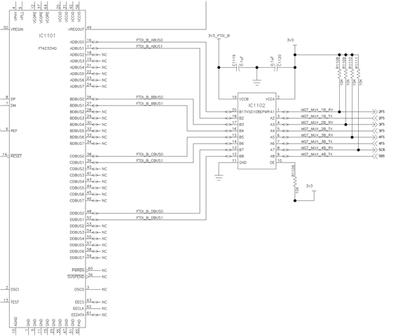
I'm using a TXS0108EPWR to buffer and translate some UARTs between a processor and an FTDI USB chip. The TX and RX pairs to the processor are all on the "A" side and the UART to USB chip is on the "B" side of the TXS0108E. Both A and B voltage levels are nominally 3.3V, but they are generated from separate supplies so that's why I have the buffer in between. I've ensured that the "B" side voltage is slightly higher than the "A" side (3.32V vs 3.28V).

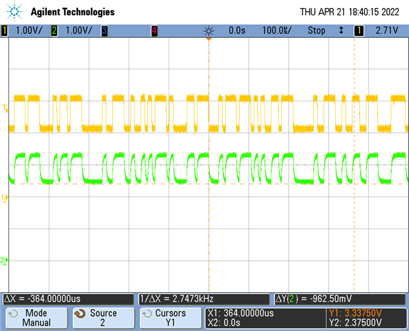
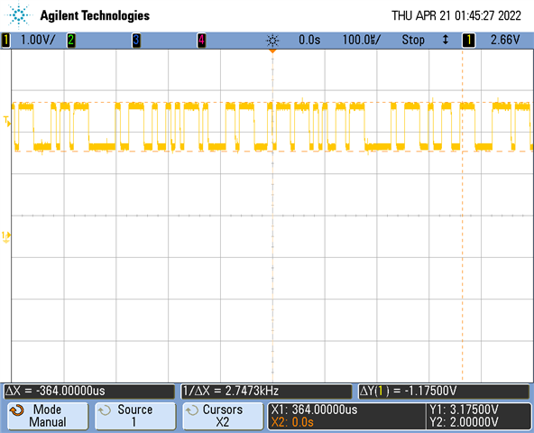
The issue I'm seeing is that the TXS0108E is clamping the UART signals high such that I only get about 1V of swing from top to bottom. Not nearly enough to properly decode the signal. Rather than a logic 0 measuring 0V and a logic 1 measuring ~3.3V, I'm seeing around 2.0V for a logic 0. See the scope plot below. Both the "A" and "B" sides match like this.

If I disconnect power to the "B" side of the TXS0108E, the "A" side starts to go the full swing again all the way down to GND. It seems like there's some issue with the "B" side clamping the A side high. I can toggle the "B" side power and watch the signal go from clamped above 2V to normal (down to GND). I've tried different A/B pairs and multiple boards with always the same results.

What's also strange is that I've used this exact same circuit before on another design and did not have this issue. The only difference is that I used the TXS0108EPWR package this time instead of TXS0108ERGYR like the older board. 

Any suggestions for what might be causing this issue and how to fix it?

  • The TXS is a passive switch. I'd guess that the drive strength of the processor or USB chip is too low for the pull-up resistors you're using, but it's hard to say without the schematic.

  • I don't have any pull-up resistors on this TX line I'm probing aside from the ones built in to the TXS0108E. Remember that when I turn off VCCB, this issue goes away and the UART signals look fine on the "A" side. As soon as I power up VCCB, the signals observed on both sides get clamped again. I've used this same design and circuit before and it worked fine. My schematic is shown below:

    Any ideas how to allow the full swing to pass through? I'd hate to have to remove and bypass this part.

  • Hey William,

    Which output is that scope shot showing? 

  • The scope plot is showing pin 3 (A2). That's the TX output from the processor to the USB chip.

  • Hi William,

    Is there a pull-up connected to B2 in any way? This device provides no DC drive of its own aside from the pull-ups. So any DC level issues you see come from something contending with those pull-ups or contending with the interfacing devices providing the DC drive. 

    It would also help to see both the input and output signal as it would indicate how much current is flowing through the device.

  • The datasheet for the FTDI USB chip doesn't include an internal block diagram so I'm not sure if it has internal pullups. However, I used the same exact chip connected the same exact way before and the design worked.

    Scope plots of input and output signals are shown below. The top/yellow waveform is on the A side at the processor going into pin 3 of the TXS0108E. It measures 2V-3.18V. The bottom/green waveform is on the B side of the TXS0108E at pin 18 and goes to the FTDI chip. It measures 2.37V-3.34V.

  • When VCCB is powered down, all I/O pins have high impedance.

    With the B voltages being higher, it looks as if something on the B side pulls the line up.

    If you just want to isolate the two devices, use a plain switch like SN74CB3Q3245 (which blocks voltages at its I/O pins even when powered down), or 2x SN74AHC4066 (powered from the supply that stays on, control inputs from the other supply).

  • That makes sense. The issue is I've already built these boards. I didn't expect any problem since I've built the same design before and didn't have any issues. What would you recommend I do on my current boards? Is there anyway to make this work without just removing the TXS0108E and jumpering between A and B?

  • The TXS never pulls DC signals down, and pulls them up only through the 10 kΩ resistors. What you see must be caused by something else (solder bridges, or some other device pulling the signal down).