This thread has been locked.

If you have a related question, please click the "Ask a related question" button in the top right corner. The newly created question will be automatically linked to this question.

SN74LVC1G11-EP: Output Voltage Drop vs Current Curve for PWM DAC

Part Number: SN74LVC1G11-EP

Hi Team,

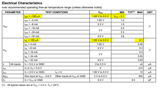
I am looking to use the SN74LVC1G11-EP as a driver for a PWM DAC and am wondering if there is any additional info on the voltage drop and rise above ground when the part is sourcing and sinking current respectively.

I want to use those to ensure I will get sufficiently low error on the output voltage after an RC filter.

The datasheet has a few currents where the Voh and Vol parameters are given but more detail in the 10uA to 1mA range would be useful.

There is also some amount of cancelling out of the two offsets, especially near 50% duty cycle but I am unsure how much affect that will actually have on the output.

I have also run a sim in Tina TI with the part and seem to get voltages accurate to ~1mV instead of the 100mV listed in the datasheet with a 100uA current draw. I assume the model for the part is not set up for worst case ranges though so it would not be a good representation of worst case values.

Thanks,

Caleb Olson

  • MOSFETs behave much like resistors. The typcial output resistance is roughly half of the worst-case one.

    See [FAQ] What is the output voltage (VOH or VOL) when the output current is X or the supply voltage is Y?

  • Hi Clemens,

    Thanks for your response. The calculated output resistance value for the 100uA current line is about 1KOhm whereas the higher currents show resistances of ten's of ohms. Would it be safe to assume that the ten's of ohms values are correct if they are at our operating voltage instead of basing it off the 1K value? Even if our current is still in the 100's of uA range?

    Thanks,

    Caleb Olson

  • Hi Caleb,

    You are correct -- the low current value is very inaccurate and it's best to use the larger current values for output resistance calculation.

    The 0.1 V value provided is a round figure, but really has nothing to do with any measurements. You will find that with 100uA in most systems that the output will be approximately the rail voltage and will be hard to distinguish from noise.

    -

    A MOSFET's resistance will vary in the Ohmic region of operation from a minimum value when I_OL and V_OL are very small to a maximum of approximately double the minimum value when the device is transitioning into the saturation region. For logic devices, you can assume that the resistance is relatively constant for all the normal operating region (ie when the output voltage is near the rails, aka when V_DS on the MOSFET is small).

  • Thanks for the confirmation! That should answer everything I have.