This thread has been locked.

If you have a related question, please click the "Ask a related question" button in the top right corner. The newly created question will be automatically linked to this question.

SN74AUP1G07: Open drain at 5V.

Part Number: SN74AUP1G07
Other Parts Discussed in Thread: SN74LXC1T45, SN74LVC1G07

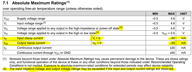
Hi! I was wondering if the open drain buffer in the title can have its output be connected to 5V via a 10kohm pull-up resistor. I'm trying to create a level shifter from 1.5V to 5V. According to the datasheet, the absolute maximum ratings for Vo when high-impedance is 4.6V, less than the output side voltage supply. However the datasheet has a footnote stating that going beyond the limits is allowed if current is monitored, which I believe the 10kohm should satisfy. However, there's another footnote saying that going beyond the recommended operating conditions does not imply functional operation. This is quite vague, so I don't know if this will actually work.

  • Hi Bradley, and welcome to the forums!

    I was wondering if the open drain buffer in the title can have its output be connected to 5V via a 10kohm pull-up resistor.

    No, the AUP family can only have up to 4.6V applied to it.

    If you just need to convert a 1.5V signal to a 5V signal, the best option would be the SN74LXC1T45, which is a dual supply translator designed for 1.1V to 5.5V operation.

    If you need an open-drain output, then a second device would be required. I would recommend the SN74LVC1G07.

    According to the datasheet, the absolute maximum ratings for Vo when high-impedance is 4.6V, less than the output side voltage supply. However the datasheet has a footnote stating that going beyond the limits is allowed if current is monitored, which I believe the 10kohm should satisfy. However, there's another footnote saying that going beyond the recommended operating conditions does not imply functional operation. This is quite vague, so I don't know if this will actually work.

    The footnote (2) that you referenced is specifically regarding clamp diodes - although I agree the wording is not as clear as I would prefer. In the past, these tables were often written assuming the reader has a certain level of experience with these kinds of parts, and we have been working on improving this in more modern datasheets to make the explanations more explicit. The "current ratings" it references are the highlighted input clamp current and output clamp current specs, which are only valid for the condition of V_I < 0 or V_O < 0.

    In other words, you cannot exceed the max output voltage rating when the output is in the high-impedance state.

    -

    With any CMOS device, you cannot apply voltages above the absolute maximum supply voltage range (in this case, 4.6V) because this will exceed the stress rating of the MOSFETs inside the device and can cause immediate breakdown and undesired current flow. You must have a MOSFET rated for the operating voltage to prevent this.

    Our AUP parts are only rated for operation up to 3.6V, and should not be operated close to 4.6V as that is getting close to the breaking point (ie the absolute maximum voltage that can be applied). The LVCxG family is designed for operation up to 5.5V, with the absolute max voltage being 6.5V.

    -

    These FAQ's may be of help for explaining a bit more:

    Can the input voltage (Vi) to my logic device be higher than the supply voltage (Vcc)?

    [FAQ] Can you pull-up an open-drain output to a higher voltage than the device's supply (VCC) voltage?

  • Ah so it is MOS VDS breakdown voltage. If that was written in the datasheet, I’d immediately know this wouldn’t work. Unfortunately the supplier I use doesn’t stock LXC parts. I could go with the LVC1T45 instead and force my circuit to work at 1.65V min input but the current draw seems a bit high. My entire current budget is 1uA in sleep mode. What if I put a 0.7V diode in series with the pull-up resistor and still keep using the AUP part in the title?

    Edit: How about both a 10kohm pull-up resistor and a 18kohm pull-down resistor so the high voltage is 3.2V instead? I realised I can get away with 3V as high, but 1.5 is way too low.

  • A diode would not work, because no current flows (except when the isolation has already broken down).

    A voltage divider would blow your current budget.

    Please note that the specified currents are worst-case values at the most extreme temperatures; typical values are orders of magnitude lower.

  • Ah right because forward voltage isn’t consistent and would be way too small at almost zero current. I forgot to add a bit more context regarding my sleep current budget. The 5V rail will go down to 0V during sleep, so the voltage divider shouldn’t affect the sleep current budget. The voltage divider should work in that case right?

  • Yes. (But then you do not have an output signal that goes to 5 V.)