This thread has been locked.

If you have a related question, please click the "Ask a related question" button in the top right corner. The newly created question will be automatically linked to this question.

D flip flop refuses to flip

Other Parts Discussed in Thread: SN74AUP1G80, SN74LVC1G80, SN74AUP1G17

Hi,

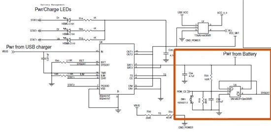
I have a simple circuit (given to me via some TI source) that allows a momentary ON Switch to toggle a D flip-flop so that the output can be used to turn on and off the battery power to the remainder of the circuit board. So, this simple circuit is always powered to allow the power switch to work, so it is very important that it consume as little power as possible. 

I planned on using the circuit 'as is' with the ultra low power SN74AUP1G80. Then I noticed the original circuit is switching 3.3V whereas I was switching a 3.7V LiIon battery. Unfortunately, the battery can charge to 4.1V which is more than the CLK input can withstand! Soooo, I put a divider, R18 = 200k, to limit the voltage on as a bandaid fix. This was only a temporary fix as the circuit is now drawing even more current.

The solution was to get a higher power flip-flop, SN74LVC1G80,  and remove R18. This solution, overall, uses less current.

It really seemed like the simplest solution. The problem is Q* stays high and does not toggle when the momentary ON switch is pulsed low on CLK!

I even tried doubling the cap value across the CLK from 0.01uF to 0.02uF, even though it does not appear to be switch bounce.

Please note, in closing, that I am without a scope, so I am hoping one of you guys will look at this and figure it out just by inspection, or give me an easy test to try that does not involve a scope.

Thanks in advance!

Kevin Kreger


  • Hi Kevin

     I see several problems.

    1. the rise time going into the clock is going to be very slow. Way out of spec. you need to add a schmitt trigger on the clock line. AUP1G17

    2. The voltage into the clock will be .66 x Vcc the Vih is .65 x Vcc so the input is kind of borderline.  Since the hi level in the clock is somewhere around 2.87V with a 4.1V vcc the delta Icc will be high.

    adding the schmitt trigger will help a lot. with the current.

    another idea it to use a diode in series with the 100k and remove the 200k. this would lower the 4.1V down to 3.4V and be in spec for AUP.

    This way  you could use AUP1G17  to speed up the clock edge and use the AUP1G80 and keep the current low.

  • Hi Chris,

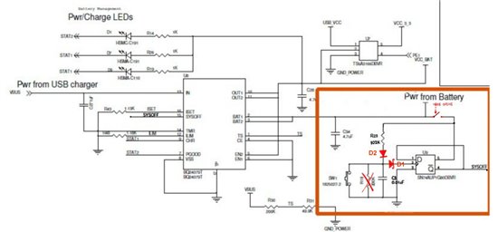
    First and foremost, thank you so much for your quick and complete reply. I definitely want to add the diode and drop the 200k so that I can continue to use the lower AUP1G17 per your closing comment. As well, it appears that adding the schmitt trigger will alleviate any clock/switch nastiness. I have redrawn the circuit with your recommendations added: D1 is the SN74AUP1G17 schmitt trigger, D2 is the diode with a ~0.7V drop.  Can you please suggest a low-power surface mount diode?

    Please note that this circuit toggles the battery management chip using SYSOFF thereby turning ON/OFF the rest of the board. To reiterate, I am trying to minimize the current consumed by this circuit and, toward that end, wonder if you have any other suggestions in that regard.

    For example, when the circuit is powered down, SYSOFF is driven high and stays high the entire time the circuit board is off. Is there an opportunity to minimize current from Q*? For example, should I put a high impedance resistor between Q* and SYSOFF? Any other suggestions component-wise (i.e. do I have the lowest power schmitt, latch, and diode?).

    Finally, I have a problem with my current circuit because it impacts the detection of whether or not the battery should be charged and how long it is charged for. So, when USB power is connected via VBUS there is enough current pulled by my original circuit (with the 200k voltage divider) to make the battery manager 'detect' a battery when none is connected. This isn't such a big problem as it is a "don't care" scenario. However, what I did notice is it takes much longer for the battery manager to charge the last few 0.01V's because of this current simultaneously trickling away. It may not be a problem with your recommendations as the current is reduced considerably, but I want to ask 2 things in this regard:

    1) How would you make sure Q* is low when VBUS is connected (to minimize current used by the latch)? 

    OR

    2) Would you add a switch that is opened by VBUS to turn this circuit off entirely? (I've sketched this below). If so, please recommend a component/circuit. Note that we don't care if SYSOFF floats when VBUS is connected as the battery management chip is 'always on' when VBUS is connected (SYSOFF is overridden).

    Thank you so much Chris. I woke up this morning and saw your post and it really has lifted a burden from my shoulders.

    BTW, I am in India at this time so we are 10.5 hours of time difference.

    Kind regards,

    Kevin

  • Sorry for the sudden change of focus, but... did you consider using a switch with mechanic retention, instead of push-button, FF, etc.?

  • Yes, and it was not a good idea as we already have the battery mgmt chip doing the switching with an internal FET, so we neither need or want a large mechanical switch. This is a small box as well.

    Thanks for asking!

    Best,

    Kevin

  • I was thinking of a mechanical switch instead of SYSOFF - It is a small current one.