This thread has been locked.

If you have a related question, please click the "Ask a related question" button in the top right corner. The newly created question will be automatically linked to this question.

SN74LVT244B: TTL 5V <-> LVCMOS 1.8V

Part Number: SN74LVT244B
Other Parts Discussed in Thread: LSF0108, TXS0108E, SN74AXC1T45, SN74LVC1T45

 Hello everyone,

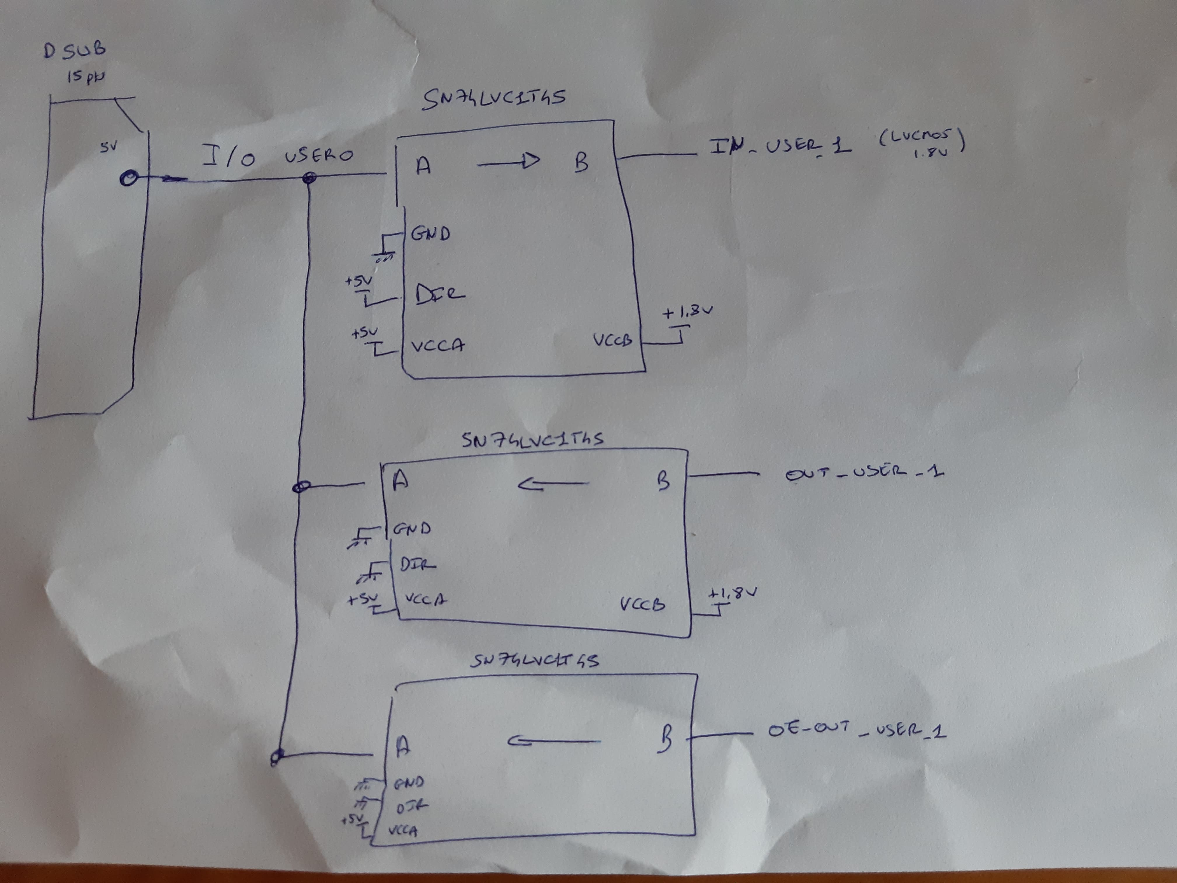
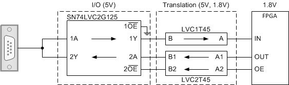
I have 3 I/O 5V TTL bidirectionnal (each signal have one input, one output and one output enable).

In my previous systems, I used this component SN74LVT244B (with 74AHC1G125GW) to have bidirectionnal translation between 5V TTL from/to 3.3V LVTTL.

Now, I want to connect these 3 5V signals to my Virtex 7 evaluation board.

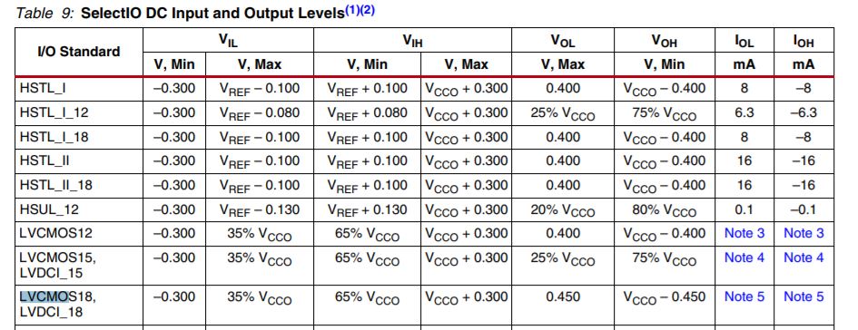
The problem is that the Virtex 7 only accepts LVCMOS 1.8V. Which component do you advice me to take?

Should I keep the SN74LVT244B  ((with 74AHC1G125GW) to convert to 3.3V LVTTL and then use another component to translate to LVCMOS 1.8V ?

Thanks for your answers and happy new year,

Thibault

  • Hi Thibault,
    Can you tell me more about your requirements? It would help if you posted a schematic or a block diagram of your system so I can better understand. Also, data rates, expected loading, and each signal's directionality would help.

    From what I see above, you need 9 total channels of translation for 3 "signals"

    If I understand correctly, each "signal" requires three channels:
    1x input (1.8V <-- 5V)
    2x output (output + output enable) (1.8V --> 5V)

    Is this correct?

    If my understanding is correct, you do not need bidirectional translation -- you need unidirectional translation (3x 5V to 1.8V, 6x 1.8V to 5V). You should be able to find solutions that will work for you in the parametric search on ti.com.

    If each "signal" is only broken into 3 different lines due to the translation, and it's actually just one wire, then you could use an auto-bidirectional translator like LSF0108 or TXS0108E -- or you could use direction controlled translators like the SN74LVCxT series.
  • Hello,

    Thanks for your quick answer :)

    I did a quick schematic of my system. Hope this can help you understand my need and precise me what option I should go for.

    I've got 3 wires (from a dsub connector) that are dividing into 9 channels  (the input and the 2 output for the 3 wires). These 9 channels are connected to a FPGA board (here Artix 7) via a cable.

    I've got another concern that is related to the distance max for lvcmos signals.

    Indeed, I want to make the adaptation for my signals on my board and connect all my lvcmos signals directy to my FPGA board via a vhdci cable (approximately 1 meter)

    Thanks

  • Hi Thibault,
    Thanks for the schematic - that helps me a lot.

    Unfortunately, there's nothing in our portfolio that will accomplish this at 250 MHz. The SN74AXC1T45 can do 1.8V to 3.3V translation at 250MHz, and although 3.3V CMOS does meet the TTL standard, I assume you mean 5V I/O's. I don't know of any 5V families of logic that can hit 250MHz.

    To get to 5V, you will have to go for lower speeds -- the SN74LVC1T45 will only get to ~37.5MHz for 1.8V translation.

    Any auto-bidirectional translator will be slower than these suggestions (ex: LSF, TXS, TXB)
  • Thanks for your response.

    Ok so if I sum up, either I can go for a 1.8V to 3.3V translator (SN74AXC1T45) at 250 MHz speed, and then use another translator 3.3V to 5V to meet the frequency requirement.
    Or either I can go for only one component (SN74LVC1T45) that will realize what I want to do but with lower speed.

    Is it correct ?
    Thanks again,

    Thibault
  • The only thing I see wrong is that I don't know of any parts that will meet 250 MHz for 3.3V to 5V translation.
  • Ok thanks for all the info, I will go with the SN74LVC1T45 then.
    I don't need the 250 Mhz for my system for the moment.

    Is my schematic correct ? I made an example for one wire among the 3 I/O that I have.

    Thibault

  • Hey Thibault,
    The 3 I/O pins can't be directly connected like this -- you will get bus contention and damage to one or all of the devices set as "output."

    If the wire on the left is actually a bus (3 separate wires) then you're fine.
  • Hello,

    No my wire on the left is not a bus.

    How should I proceed then to have an input or an output (controlled by OE) on a single wire with SN74LVC1T ?
    Knowing that my 3 right signals are 1.8V voltage and my left signal is 5V.


    Thanks

  • Hey Thibault,

    My recommendation would be to separate out your translation and I/O stages like this:

    I didn't include every signal, but I hope it makes sense.