


I wish to do an experiment with the CD4514BM96 demux with the MSP430G2 launchpad. Before purchasing the demux, I have some questions.
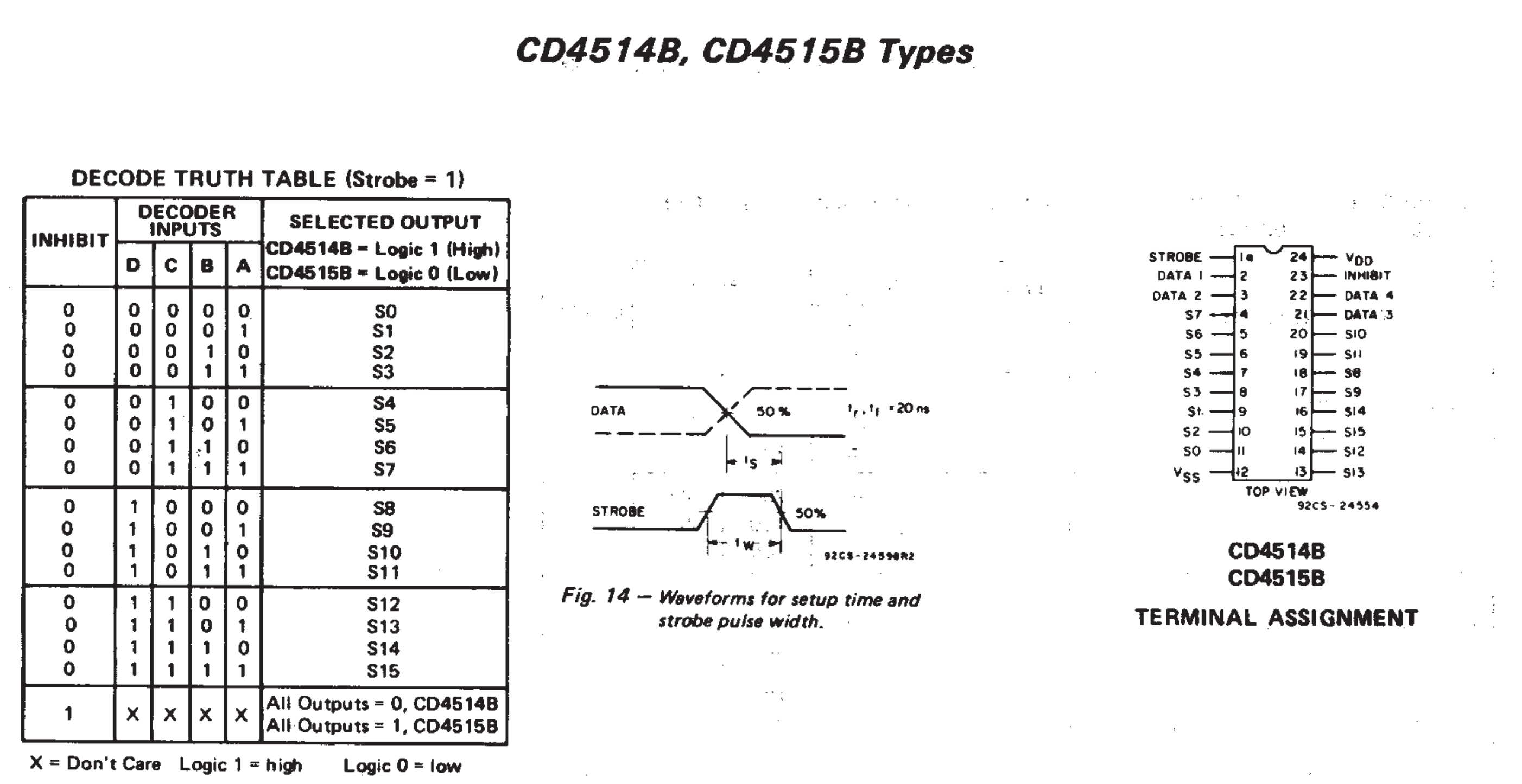
Q1. Does the decoder input (Data 1,2,3,4) voltage level has to be similar to VDD?
For instance, I wish to connect VDD = 15V and the decoder inputs to the MSP430's 3.3V GPIO pins to control the output.
Or do I have to connect 15V to the decoder inputs?
Q2. What does the strobe pin do?
Q3.
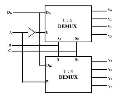
Just like this picture, I was looking for a data input Din pin.
However, I cannot find it from the CD4514BM96. Is there a data pin?
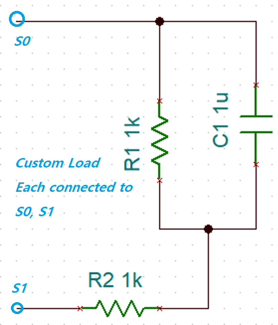
Q4. If I connect the load's terminal to output 1 and 2 to control the load current's polarity, will this damage the DEMUX?
