This thread has been locked.

If you have a related question, please click the "Ask a related question" button in the top right corner. The newly created question will be automatically linked to this question.

SN74HC595: SN74HC595

Part Number: SN74HC595

Due to a circuit failure with a SN74HC595 shift register in circuit, an engineer measured the input resistance of a "good" similar IC between the "SRCLR"(not) and the "SRCLK", pins 10 & 11 respectively, with

a Keysight "micro-ohm" resistance meter. This was measured from pin 10 to 11, i.e. pin-pin, in a no Vcc applied environment.. Later he realized that the meter at the very low resistance scale was applying an 11.3V potential to the paired pins when the input resistance measured was near 800k ohms. So the question is, given the meter applied voltage was the IC stressed in any manner that would possibly cause a reliability issue over time? Again, no Vcc was applied to the IC at the time.

Thx in advance.

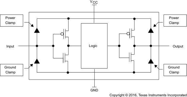
  • To get a current between two input pins, a reverse-biased clamping diode or some gate isolation must break down.

    And a current of 14 µA is larger than any normal leakage current, which implies that some breakdown voltage indeed got exceeded.

    Anyway, with VCC floating, the input voltage is not clamped. So if one gate had a voltage of more than the absolute maximum rating, then it is possible that you have a problem; the AHC/AHCT Designer's Guide (SCLA013) says:

    Input voltages greater than 7 V must be avoided to preclude damage to the gate oxide of the input stage. This damage is not necessarily permanent, but will adversely affect the expected lifetime of the circuit. The gate oxide of AHC devices is only 200 Å thick. An input voltage of 7 V corresponds to a field strength over the gate oxide of 350 kV/cm. Although breakdown of the oxide is expected only at input voltages above 10 V, electrons tunnel increasingly into the gate oxide at field strengths greater than 350 kV/cm, influencing characteristics of the transistors and causing failure.

  • Clemens,

    Much thanks for your reply.

    One question the 11.3V was not applied to a singular pin, i.e. referenced to ground, but across two adjacent pins. Is not the 7V maximum voltage per pin a voltage that is referenced to ground? So assuming the input ports are isolated, each has a buffer amp at it input, does the 7V max rating still apply?

    Thanks in advance.

  • Some of the clamping diodes can be forward biased, so the chips internal VCC will be at about 10.6 V, and the internal GND at about 0.7 V.