This thread has been locked.

If you have a related question, please click the "Ask a related question" button in the top right corner. The newly created question will be automatically linked to this question.

SN74LVC1G14-EP: SN74LVC1G14-EP strange behavior

Part Number: SN74LVC1G14-EP
Other Parts Discussed in Thread: SN74LVC1GU04

A client of mine is using a SN74LVC1G14-EP as an analog discriminator where it is driven by an analog op amp and powered from 3.3v.  The power rail and ground are stable. 

The SN74LVC1G14-EP is acting like an inverting analog op-amp with a gain of around -1.5. 

For example, if a sine wave is present on pin 2, pin 4 (the output) is an inverted sine wave of slightly higher amplitude.  This exists even down at 10kHz. If the input is changed to a square or triangle wave, the output is similar shape, but inverted.

The part marking is "SBLM".   

Is there any condition where this part should act like that ? 

Is there an underside part marking or any other identifiable checks for counterfeit ? 

  • A Schmitt-trigger inverter should never output an analog voltage.

    What is the amplitude of the input? Can you show oscilloscope traces?

    An opamp without negative feedback would not result in a gain of −1.5. If you have a wrong device, I would guess it is an unbuffered inverter, e.g. SN74LVC1GU04.

    Can you check that the input impedance (to VCC and GND) is approximately infinite?

  • Steven,

    I agree with Clemens.  A digital output cannot drive a sine-wave output.

    Please provide schematic, and scope shots of input and output.

    If you think devices may be counterfit, then you will need to do the following:

    Please contact the TI Anti-Counterfeiting Team at ti-counterfeit@list.ti.com.  In your email to them, request the Customer Letter and Counterfeit Request Form and provide them with the required information below. 

    • Completed Counterfeit Request Form
    • High quality pictures of the bottom & top of the device(s)
    • High quality pictures of the 2D bar code labels.
    • Copies/pictures of shipping documents, i.e. packing slip showing the origin of the devices to TI. (If this information cannot be provided we are unable to provide verification due to uncertainties regarding chain of custody of the products.)
    • Provide device application

    Regards,

    Wade

  • Wade and Clemens,

    Thanks for the ultra quick response!

    Here is some more info to work with: 

    - Measuring the pin2 (input) to either pin 5 /3 gives open circuit with a meter (part is off the board) 

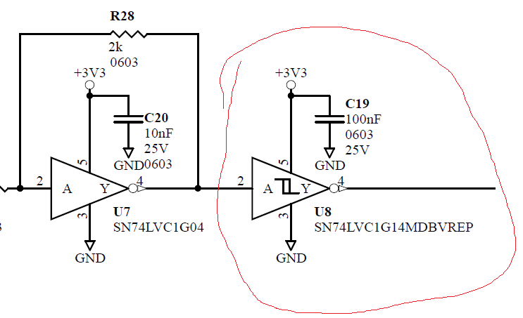
    - Here is a schematic snippet:

    Here are scope shots showing @ 500kHz:

    -Ch1: input(pin2) and Ch2: output(pin4):

    -Ch1: 3.3v(pin5) and Ch2: output(pin4) :

    - Ch1: GND(pin3) and Ch2: output(pin4):

    Here are top and bottom pics of the part itself when removed from the board: 

  • Wade and Clemens, 

    There is something not very obvious going on with the PCB or circuit, but I'm definitely sure the problem isn't the TI part. 

    Replacing the TI part with an NC7S14M5X (which is a pin for pin match schmitt trigger inverter), also gives a strange analog response. 

    Thanks again for your excellent response time !

    Steve 

  • Thanks for closing this out.

    I was suspecting poor power or ground. 

    Regards,

    Wade