This thread has been locked.

If you have a related question, please click the "Ask a related question" button in the top right corner. The newly created question will be automatically linked to this question.

SN74LVC245A: Output Voltage Level

Part Number: SN74LVC245A
Other Parts Discussed in Thread: UCC23513, LM334

Hi, 

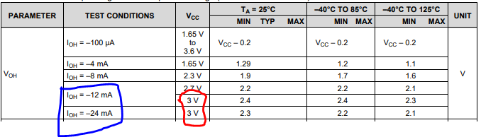
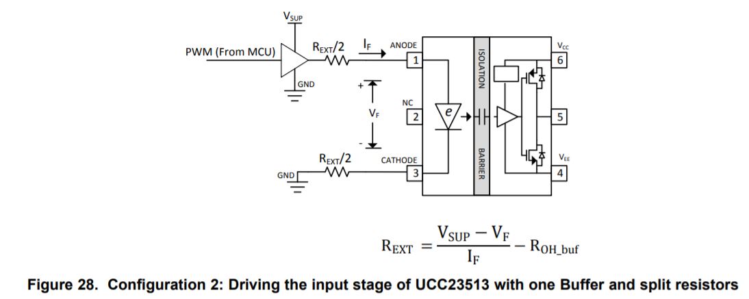
My customer is using SN74LVC245A to drive UCC23513, the power supply of SN74LVC245A is 3.3V, input PWM signal frequency is 20KHz. They check the datasheet of UCC23513 and found the maximum open voltage VF is 2.4V, so they concern that SN74LVC245A will have risk to drive UCC23513. Could you please confirm the minimum high-level output voltage of SN74LVC245A? Would it possible to drop below 2.4V? Thanks.

Regards.

Chen

  • Hi Chen,

    Page 6 of the LVC245 datasheet mentions the Voh / Vol electrical specs for the device. The min high voltage depends on the current loading/ operating temperature and it can be as low as 2.4V at 12mA current loading across -40 to 85C for 3V Vcc operation. With higher Vcc level of 3.3V, it would be slightly higher than that. I see that the IF of the UCC23513 device is listed as 10mA, hence the LVC should be able to have Voh>2.4V.

  • Hi Chen,

    It just so happens this is spec'd in the DS.

    I think it will be fine.

  • Hi, Dylan

    Thanks for your reply. Customer refered to the UCC23513 DS Figure.28, assume IF=10mA, and use a REXT= 114Ω. But there is a problem that if the output high level voltage of LVC245 is 2.75V due to DS figure 6, and the VF of UCC23513 is 2.4V, the IF is (2.75-2.4)/114=3mA, can't drive UCC23513. Do you have a IOH VS VOH figure like LVC245 figure 6 under 3.3V, and with different temperature conditions? 

    Best Regards

    Chen

  • The  SN74LVC245A datasheet shows the worst-case for a nominal 3.3 V supply that has a tolerance of ± 10 %. If the actual power supply is not as bad as that, then you do not need to assume VCC = 3.0 V.

    And the UCC23513's minimum recommended IF is 7 mA.

    So, assuming VCC drops to 3.2 V in the worst case, REXT = (3.2 V − 2.4 V) / 7 mA − 25 Ω ≈ 89 Ω.
    In the typical case, this results in a current of (3.3 V − 2.1 V) / (89 Ω + 25 Ω) ≈ 10.5 mA.

    With a VCC that is not much larger than  VF, it is hard to regulate the current. If it is not possible to use a higher VCC, you might consider using a constant current source (LM334 or discrete).

  • Hi, Clemens,

    In you calculation, REXT = (3.2 V − 2.4 V) / 7 mA − 25 Ω ≈ 89 Ω. It meansThe on-resistance of LV145 is 25Ω, is it tested or experiential value? I didn't see this value in the datasheet.

    Best regards,

    Chen

  • It's a typcial value for LVC outputs; you can see it in the graph above (0.5 V / 20 mA).

  • I can't get your point. Why 0.5V/20mA? And these logic devices usually use CMOS process, the on resistance can't be so large, can you double check it?

  • The line goes from 3 V / 0 mA to 2.5 V / −20 mA.

    LVC is the CMOS family with the strongest output drivers; other families have higher output impedances.