This thread has been locked.

If you have a related question, please click the "Ask a related question" button in the top right corner. The newly created question will be automatically linked to this question.

SN7407: Not getting the proper output

Part Number: SN7407

Hi TI,

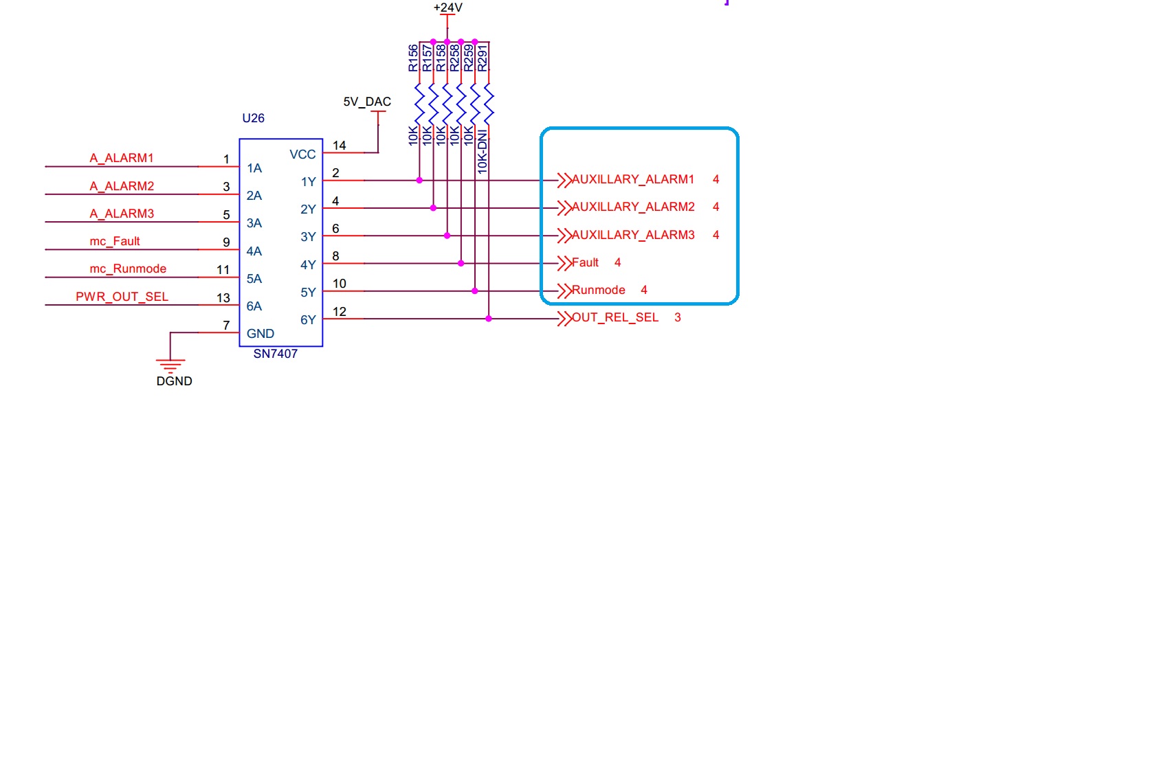
We are using SN7407 part to boost up the voltage from 3.3V  to 24V output by adding the 10K pull up resistor in output end, Please see the below image from schematic. But we are getting only 3.2V output, Please suggest on this.

Thanks,

Dinesh KS

  • Hi Dinesh,

    I suspect the issue is related to the coil at the output. Can you show the full load circuit?

  • Hi Emrys Maier,

    Below is the circuit.

    Thanks,

    Dinesh KS,

  • Hi Dinesh,

    Currently, your circuit is connected like this:

    As you can see, there's a voltage divider between the 10kohm and 1.6kohm (coil) resistances, so when the open-collector output is off (no current flows into the driver), then you will expect to see about 3.3V at the output. (Vout = 24 * 1.6k / (10k + 1.6k) = 3.31V)

    Additionally, this circuit is _always_ using up power at the output -- either current is flowing through the coil, or current is flowing through the driver, but either way the 10kohm resistor is using up power.  You _could_ make this work by reducing the 10kohm resistor to a much lower value, thus increasing the current flowing -- but you might not be able to get enough current this way.

    A better solution would be to change your configuration to this:

    In this configuration, when the driver is off, then the relay coil is also off and there is no power consumption from this part of the circuit.  When the output is on, then it sinks current and the coil works as expected (~15mA of current through the coil).

  • Hi Emrys Maier,

    You prepare any particular diode part number?

    Or shall we use the same 1N4007FLTR diode?

    Please suggest on this.

    Thanks,

    Dinesh KS.

  • Hi Dinesh,

    TI doesn’t offer discrete diodes, so I can’t really suggest a particular device.


    I don’t see a problem with your original selection – I just moved the coil + diode in the circuit. You can probably get away with a much smaller diode -- it's only going to be seeing about 15mA of current through it and only needs to protect against 24V reverse voltage.

  • Hi Emrys Maier,

    Thanks for the information, will implement this circuit and will let you know the status, Also I need one more confirmation for below point.

    5 signals marked in the below image are connected to 24V LED directly, whether this will work or not?

    LED Pars link is below.

    https://smile.amazon.com/gp/product/B07DK4G38R/ref=ppx_yo_dt_b_asin_image_o00_s00?ie=UTF8&psc=1

    Thanks,

    Dinesh KS

  • Hey Dinesh,

    You may want to post these kinds of questions to a forum with more of a DIY type base (DIY Electronics on Reddit or the Electronics Stack Exchange are quite good in my experience) -- this forum is really dedicated to helping engineers developing products with TI's parts who encounter challenges. Not that I mind helping, but I would give quite different advice if I weren't a TI employee and speaking on behalf our company, if that makes sense. I can't really be seen to recommend other company's products or provide advice beyond the products I support.

    That being said, you can connect an LED + series resistor directly to the output of our device. If the comments I read on Amazon were accurate, then the LED you are using already includes a resistor, so you don't need the 10k resistors. You'd just hook the cathode of the LED module to +24V, then the anode to the output of the '07.

    * Don't take my word for it though -- check into the datasheet for the LEDs to be sure they won't burn up if connected directly to +24V. *

  • Also, in the below circuits, Auxillary_ALARM1-3, Fault, and Run mode signals are connected 24V relay and same connections are made between microcontroller to LED for these 5 signals.

    We are getting the proper output and function for Auxillary_Alarm1-3 LED,

    But for some reason, 24V LED continually glowing/on in the Fault and Runmode side, also we are getting 1.6V from the input side of the IC for Fault and Runmode.

    Please suggest me this.

    Thanks,

    Dinesh KS.

  • Hi Dinesh,

    Your LED circuits aren't shown above. I'll need to see those to help.

  • Hi Emrys,

    The output from U26 are going to a jumper, from which there are directly connected to the LED. 

    The Red color is hooked up to AUXILLARY_ALARM1, Yellow connected to 2 and 3.


    https://smile.amazon.com/gp/product/B07DK4G38R/ref=ppx_yo_dt_b_asin_image_o00_s00?ie=UTF8&psc=1

    https://smile.amazon.com/gp/product/B07DK86Q31/ref=ppx_yo_dt_b_asin_title_o00_s00?ie=UTF8&psc=1

    They need 24V to operate and are working fine with the uC (turning on and off,) however from pins 8 and 10, the output seems to be stuck at 24V even if we are providing high and low from the uC. Will this be enough?

    Please let me know if you need any additional details. 

  • Hey Dinesh,

    To troubleshoot a circuit, first I need to see the full circuit.

  • Hey Dinesh,

    I thought of something that might help.

    This is the appropriate circuit to drive an LED from an open-collector output:

    You need two pieces of information to determine your R value, which are the forward current and forward voltage of your LED.

    Using KVL you get this equation: 24 = V_OL + V_LED + V_R

    And from Ohm's law (and KCL) we know that V_R = I_LED * R

    You can rearrange to solve for R, but in your case I'm betting that the LED housing already includes a resistor, so all you really need to do is connect it as shown above and remove that 10kohm resistor.