This thread has been locked.

If you have a related question, please click the "Ask a related question" button in the top right corner. The newly created question will be automatically linked to this question.

SN74LVC1G08: Logic part get damaged

Part Number: SN74LVC1G08
Other Parts Discussed in Thread: SN74LVC1G17

Hi!

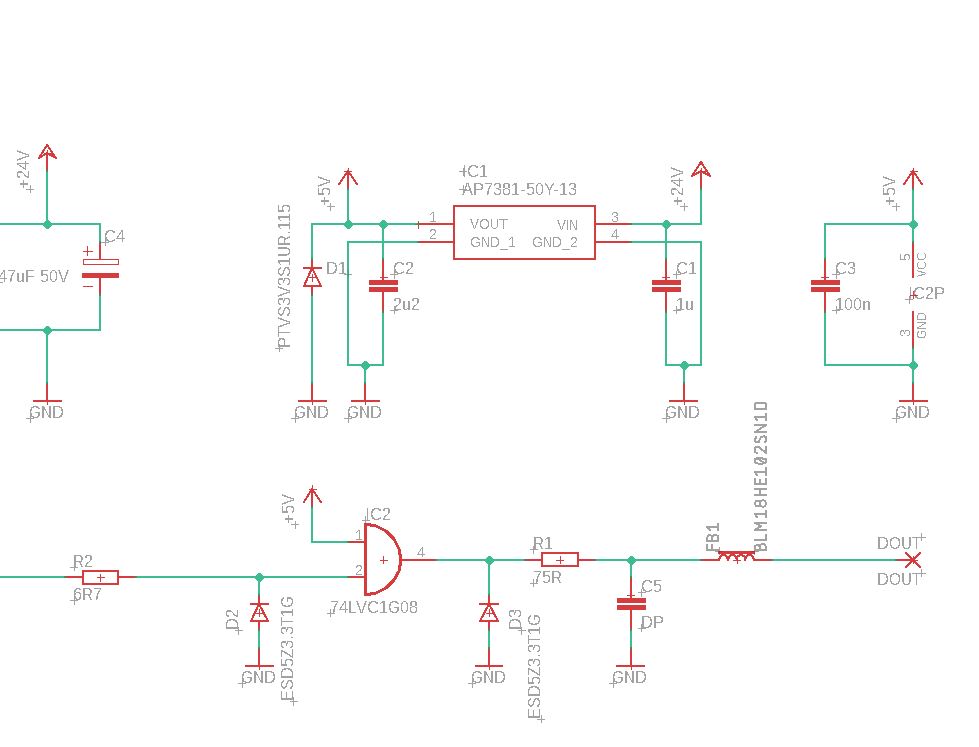
We use this circuit as a logic signal amplifier. Our system looks like that we have a:

1. signal transmitter
2. signal-power cable
3. signal amplifier circuit based on SN74LVC1G08DBVR
4. installation consisting of LEDs.

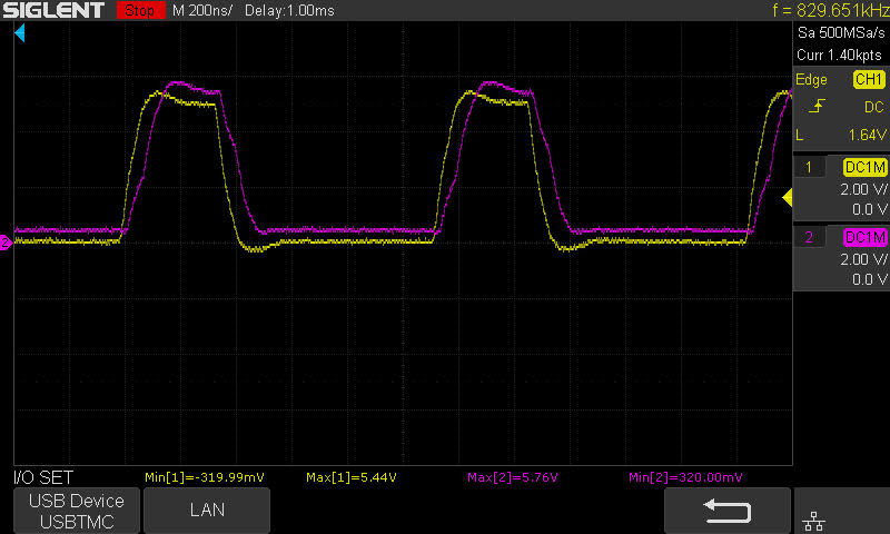
The SN74LVC1G08DBVR module is damaged after some time of operation and reduces the amplitude of the signal sent from 5V to +/- 1-2V. It is still possible to read the appropriate signal shape, but its level drops drastically.

We noticed that heating the system with hot air instantly "fix" the problem and it works properly for the next few hours. After some time, the signal is degraded again. Failure does not always occur. We use several such modules and some of them get damaged and others work without problems.

What could be the problem? Have you encountered a similar case?


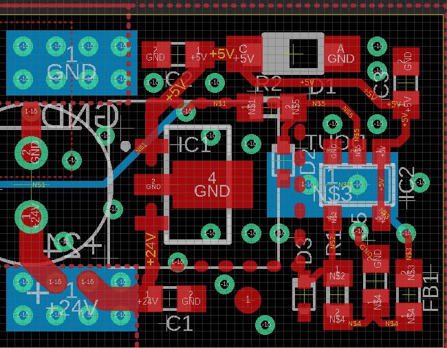
The module layout is attached.

Thanks,
Peter

  • The most likely cause is overvoltage, or an overloaded output.

    Please show the schematic.

  • Here is our schematic for this module:

  • Hi Piotr,

    In regards to the LVC1G08:

    What does the input signal look like? You mentioned using it as an amplifier, so I'm concerned that you aren't putting in an appropriate logic signal (less than VIL and greater than VIH with fast edges). Seeing a scope shot of the input/output under normal conditions would be ideal.

    Also, I would recommend increasing R1 to at least 100 ohms to prevent over-current from the device. As it is, the current limit of 50mA could easily be exceeded.

    -

    I was wondering about the power circuit and power requirements for this board -- it looks like there's a linear regulator dropping 24V to 5V, which is a very large voltage drop for a linear regulator. I could be wrong though - I only see the pads and voltages labelled. How much power is being dissipated in this board? Could your regulator be going into a lockout mode?

  • There should be a resistor between D2 and IC2. Otherwise, the weaker internal ESD protection of IC2 would see the same voltage as D2. The same applies to D3. (In general, ESD protection components should be directly at the external connector.)

  • Hi Emrys,

    Thank you for your reply. 

    The device as we call "amplifier" is used for conditioning TTL signal. 

    TI_AMP.png

    At this figure we can see two channels, yellow for the input signal and purple for the output. This one was created with use of 5m cable before and 5m cable after the amplifier, with 10A current going through the supply lines. You can see GND level change because of that. 
    TI_AMP_10m.png

    Next figure shows 10m long cable before the amplifier. It makes the GND level even lower. 
    Do you think the input signal low level could be reason for the damage? We have tried to do so, but we have never burnt this IC when we wanted to, it was always sporadic. 

    Thanks, Tom.

  • Hi Guru, 

    Thank you for your reply. 

    You have a point, we will probably place extra resistors at the input and output of IC. 

    Best, Tom

  • Hey Tom,

    Your images didn't come through. There's an FAQ on how to post images here: [FAQ] How to insert an image in your forum post.

  • Ok, sorry. Here are pictures again:
    5m cable:

    10m cable:


    Best, Tom

  • Hey Tom,

    If the input signal gets to be more than 0.5V below ground, then it will activate the negative input clamp diode on the device and could end up drawing a lot of current / causing damage. Adding some extra series resistance at the input would prevent this from happening (at least preventing damage).  The limit is 20mA for the device, so 1kohms should work well to prevent issues. For normal operation, that won't cause any side effects since the input is very high impedance already.

    The two big problems I see are that your input transition rate is slow, and your output is overloaded.

    The input signal transitions in about 100ns. At 5V supply, the LVC1G08 needs an input that switches in about 25ns (check recommended operating conditions table for the exact spec).

    Since you're not using the device as an AND gate, but as a buffer, you could switch to the SN74LVC1G17 to avoid the first issue. It has Schmitt-trigger inputs, so slow signals aren't a problem  You'd still need to limit the output current some though, as that is certainly overstressing the device.

    There's an FAQ on why slow input signals are bad for CMOS logic here: [FAQ] How does a slow or floating input affect a CMOS device?

  • Thank you Emrys for your advices. 
    I will increase the input resistance as much as impadance allows me. 
    As for shoot-through current, is it possible to be the reason for the damage? When the IC gets damaged, it does not stop working permanetly, but behaves unstable. Input impedance get decreased and you can see the input signal amplitude lowered from 5V to about ~2V. Is it possible to determine from the CMOS structure that if the input signal is lowered it means there was a problem with the input signal, not output?


  • Hey Tom,

    I don't have a good explanation for the issue you're seeing - if you can get a scope shot of the incorrect operation with the input, output and supply all referenced to the device ground, maybe I'll spot something specific.

  • Hey Emrys, 

    Thank you ones again. 
    There is one final question - this conditioning device can be unpluged during work and because of 47uF capacitor, it has supply for a few more seconds while the input is already floating. As far as I can understand, for the 74LVC1G08 it could be harmful, but for schmitt-trigger buffer SN74LVC1G17 it should be ok?

    Greetings, Tom

  • Hi Tom,

    Yes, the inputs can be left floating on a Schmitt-trigger device without concern for damage - but the floating input may result in random outputs.

  • Thank you for all of the support. We have implemented your solution with SN74LVC1G17. It works well for now. We are waiting for the posiible damage ;) 

    All best 
    Tomasz