This thread has been locked.

If you have a related question, please click the "Ask a related question" button in the top right corner. The newly created question will be automatically linked to this question.

SN74HC164: Tsu question

Part Number: SN74HC164

Hi Team,

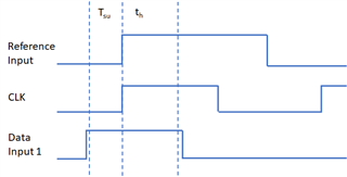
I would like to know what the mean of the tsu. 

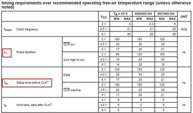
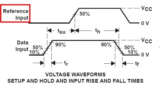
I read the data sheet, it says "set up time before CLK", but in the picture, I didn't understand the meaning of the picture.

  • What does reference input refer to?
  • Why does tsu start with the rise of data input and end with the rise of Reference?
  • What does tsu show?

Thanks for your help in advance!

BR

Jenson

  • Jenson,

    The reference input is the essentially the waveform you're aiming to produce. It would be the waveform if you didn't take into account setup (tsu) or hold (tg) time. 

    tsu is the setup time. This is how much time before the CLK's active edge that the data needs to be stable, meaning it needs to stay in the same state. So from the original Reference Input signal, the signal needs to become high earlier to be stable through at least the start up time. So you'll see on the Data Input signal starts one unit of Tsu earlier. This ensures that the correct data is latched properly.

    Thanks,
    Rami

  • Hi Rami,

    Thanks for your help.

    As your mean, Data Input signal starts one unit of Tsu earlier,I can understand this,but at this time, I think the reference input is clock.(This is how much time before the CLK's active edge that the data needs to be stable).

    so,the data input is A/B input?and reference input is CLK?


    Thank you again 

    BR

    jenson

  • Hey Jensen,

    I wouldn't necessary call this the clock. That's not to say the clock couldn't look like reference signal, however. The figure is drawing the assumption that by showing you the setup time and hold time location you can come to the conclusion that this is where the rising edge of the clock would be.
    The reference input is more so what your input signal would look like if you didn't take into consideration things such as hold time or setup time. The device stores the results of A AND B at each positive clock edge but it requires that you meet the proper setup and hold time around that rising edge. The figure shows the minimum timing considerations you should take to actually see the change in the reference input at the clock edge that you're aiming to see the change at. Because it only stores this data at the rising edges, there is some leeway in how the A/B inputs can actually look and still receive the same output. Again, the Tsu and Th are just the minimum.

    For example, below you may want to store the reference input signal at the CLK rising edge but to do so you'll need to have a signal that looks at the very minimum as 'Data Input 1' does. You could always hold the signal high earlier than the start of Tsu and later then the end of Th but this wouldn't change the output until you see setup time for the next CLK rising edge. Changing the data input while in the setup or hold time can lead to unstable outputs. 


    I hope this clears things up,
    Rami