A related question is a question created from another question. When the related question is created, it will be automatically linked to the original question.
If you have a related question, please click the "Ask a related question" button in the top right corner. The newly created question will be automatically linked to this question.
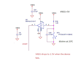
SN74LVC1G17: SN74LVC1G17 VCC and GND are close to short .
Sorry, it's not quite clear what you're asking here. When Vcc is shorted to GND your current will spike and can cause damage to your device. Are you aiming to find the root cause of your short? Could you provide more detail on what you're observing here? Providing a schematic, image or waveform of what you're seeing can help me identify the cause of the short.
I think he's trying to say that he is having these devices fail, and when they do, they exhibit a very low resistance between the power pin and the ground pin. That in turn, pulls down his power rail and shuts the rest of the board down. And it has probably happened multiple times. My bet would be on electrical over stress (EOS), generally caused by static discharge, or perhaps a power supply that isn't well-behaved at power-on or power-off. I would start by looking at the power pin and the I/O pins during power cycling, and make sure that all that looks ok. If that's ok, I'd look for static discharge paths. Is this connected to a user interface (keyboard, cable, push button, etc)?
There are a lot of possible causes, and we need more information to help sort it out.
Have you cycled the power and checked what the I/O pins and the power going into the device look like as Dale above recommended. This will help debug and find the cause. If you have any waveform screenshots I could get eyes on that would be useful as well. When you removed the device, did you put a new one on or the same one? I'm looking to see here if it's a problem with the particular chip has been fried or if this is a reoccurring problem with the setup o the chips tolerances.
Could you also provide a schematic of your setup as well?
Thanks for sharing the circuit could you provide any of the information from the request I made above? Dale had some good suggestions as well. Have you replaced the chip? Have you checked for any shorts on the board itself?
Have you cycled the power and checked what the I/O pins and the power going into the device look like as Dale above recommended. This will help debug and find the cause. If you have any waveform screenshots I could get eyes on that would be useful as well. When you removed the device, did you put a new one on or the same one? I'm looking to see here if it's a problem with the particular chip has been fried or if this is a reoccurring problem with the setup o the chips tolerances.
My bet would be on electrical over stress (EOS), generally caused by static discharge, or perhaps a power supply that isn't well-behaved at power-on or power-off. I would start by looking at the power pin and the I/O pins during power cycling, and make sure that all that looks ok. If that's ok, I'd look for static discharge paths. Is this connected to a user interface (keyboard, cable, push button, etc)?
The device can still operational at 2.5V so can you clarify more on what you mean 'when the device fails'? Does it stop functioning you aren't seeing the proper output or does the power supply drop to 2.5V and that's considered a failure in your analysis? Once again, waveforms would be helpful here.
From the information you've provided it's a little difficult to see what the cause would be. Are you taking any ESD precautions when handling the devices? This could be due to electrical discharge if it's happening periodically in random devices.
What are you aiming to do here? This buffer will just output the VCC level when you cross the threshold. Is your aim to trigger something at a given temperature? You wouldn't be digitally converting a temperature with your setup rather sending a high signal after a certain temperature range is crossed.
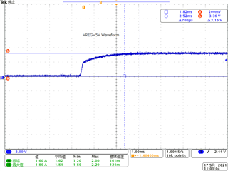
Further a scope of the power helps minimally without being able to see what the I/O signals also look like at the same time. Could you provide a scope with the I/O so we can see what's happening and if there's anything in the I/O's that could be causing this. I'm not sure what scope 4 is showing or if it's even relevant but it's picking up 1.6A which would be too high for this device. My only other thoughts would be regarding the current. You're going to have a current spike when your biasing the inputs as you are. I'm not sure if this would be a problem with your regulator. With CMOS inputs you'll typically want those inputs to be at the rails. I don't have any input scope shots here but from your circuit you sent it looks like you wouldn't be at the rails but whatever the voltage would be with the divider between the 1.2k and thermistor, which would be low.
It looks like you are using this as an overtemperature protection for the motor. So I assume the PTC is thermally coupled to the motor or the motor driver device? So that when the PTC exceeds about 110C, the START line is driven low to prevent starting the motor. You need to put the scope on the VCC line and the input to the LVC17, and look at it during startup and shutdown, and also while the motor is running. It is possible that you are getting some noise spikes inductively coupled into the input when the motor is switched on and off. If that is the case, you might need to add a resistor-capacitor filter on the input to the LVC17, and mount it physically near the input pin. It is also possible that there is an inductive spike generated on the VCC rail when the motor is turned off. Do you have a diode snubber around the switch for the motor? And look for opportunities for ESD both in assembly and in use. You have a good ESD process control in your assembly area?