This thread has been locked.

If you have a related question, please click the "Ask a related question" button in the top right corner. The newly created question will be automatically linked to this question.

SN74AUP1G74: CLR_not Capacitor - Resistor connection

Part Number: SN74AUP1G74

Support Path: /Product/Development and troubleshooting/

Hi,

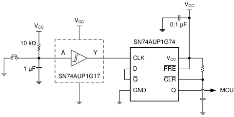
I would like to use the SN74AUP1G74 D-FF In my application.

As mentioned in the DS in page 16, there is a possibility to connect the CLR_not pin to Vcc via Resistor and capacitor.

I have some concerns with this type of connection as the DS doesn't give any guidance or specific values for the resistor & capacitor as this is an analog connection to a digital pin.

It is mentioned in the DS that the pin's voltage rise rate has to be less then 200nS/V.

I would like to know if such connection is accepted and what are the recommended values for the resistor and capacitor.

Thank you. 

  • The RC filter at the button (connected to CLK) has a time constant of 10 ms, so it needs a Schmitt-trigger buffer (as shown) to speed up the raising edge.

    But the CLR pin does not need deboucing; it just needs to be low for a short time after powering up. The datasheet says that the minimum pulse duration is 2 ns; you can simply make the RC filter at the CLR pin fast enough so that it's still inside the rise time limit. For example, 1 kΩ and 100 pF results in a time constant of 100 ns. (These value might need to be tweaked if your power supply starts up slowly.)

  • Hi Eli,

    This is a mistake in the datasheet.  You should always have a Schmitt-trigger between an RC circuit and a standard CMOS input, such as the input at CLR. The input to CLK is using the correct method.

    I will take a note to get this updated as soon as possible to eliminate confusion. Thanks for bringing it to our attention.