This thread has been locked.

If you have a related question, please click the "Ask a related question" button in the top right corner. The newly created question will be automatically linked to this question.

SN74HC595: queries regarding driving 7 segment display

Part Number: SN74HC595
Other Parts Discussed in Thread: SN74LV4T125

Hi Team ,

One of my customers intend to use SN74HC595 for driving 7 segment displays. Following are the queries regarding the same:

  1. Continuous output current is +/-35mA, does it mean that output pin can source as well as sink? Which is preferred one to drive 7 segment  display?

  2. What is the High-level input voltage (min) for Vcc 5V?

  3. I believe, if I drive input pins (SER, RCLK, SRCLK, SRCLR..) with 3.3V from micro then output pins (Qa to Qh) voltage will be Vcc i.e., 5V.

 Regards,

Harmeet


  • Hi Hameet,

    First, we have a reference design that specifically covers this application, so you might want to look that over: 

    To answer your questions individually:

    1. Continuous output current is +/-35mA, does it mean that output pin can source as well as sink? Which is preferred one to drive 7 segment  display?

    Yes, each output can both source and sink current.  These are balanced CMOS outputs, meaning that the high or low impedance is equal on each output, so it doesn't really matter which way you go. 

    What's more important is the total current the device can support (70 mA) -- note that if you have all 8 channels driving an LED, the maximum current they can support is ~8mA.  If you need more current, a buffer or driver should be added after the HC595.

    2. What is the High-level input voltage (min) for Vcc 5V?

    V_IH(min) for 5V is directly related to the 4.5V level given in the datasheet.  It lists 3.15V for 4.5V.  To get the 5V level, just add 0.5V and you have 3.55V.

    3. I believe, if I drive input pins (SER, RCLK, SRCLK, SRCLR..) with 3.3V from micro then output pins (Qa to Qh) voltage will be Vcc i.e., 5V.

    This is not a good idea primarily because of the current increase that will happen due to the lower input voltage - CMOS inputs are intended to be held close to Vcc or GND, and any value between those will cause shoot through current. This current can be large enough to cause damage to the '595.

    I would recommend adding a voltage translator such as SN74LV4T125 between your HC595 and the controller.

  • Hi Emrys,

    Thanks for your comments.

    Could you explain in detail the point no 3 with the diagram? How shoot through could occur?

    As per me it will result in not reliable switching as the minimum high input level required will be 3.5V (0.7X Vcc)  for 5V Vcc.

    Regards,

    Harmeet

  • Hi Harmeet,

    Shoot through current is caused in CMOS devices when the pFET and nFET are turned on at the same time.

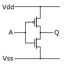
    For an example, imagine that you have a CMOS inverter for an input (which is very common) with this schematic:

    The control voltage for the pFET is V_SG = Vdd - V(A)

    The control voltage for the nFET is V_GS = V(A) - Vss

    For our example, let's make the thresholds 0.5V, Vcc = 5V, and Vss = 0V.

    When V(A) = 2.5V, then V_SG = Vdd - V(A) = 5 - 2.5 = 2.5V, which is greater than the threshold of 0.5V, so the pFET is turned ON

    Similarly, V_GS = V(A) - Vss = 2.5V - 0V = 2.5V, which is greater than the threshold of 0.5V, so the nFET is turned ON.

    Now there is a direct path from Vcc to Vss, where current will flow freely.  This is called "shoot-through current" and is a basic concept in any CMOS circuit.

  • Hi Emrys,

    What is the IOH in shift register?

    In datasheet IOH  is 7.8mA at 6V. Does IoH depends on driving voltage?

    what is the maximum current which we could get at 5V?

    is there any part in which we could more than  8mA at 5V/3.3V?

    Regards,

    Harmeet

  • Hi Harmeet,

    What is the IOH in shift register?

    IOH is _not_ the maximum output current of the device. It is the current at which VOH, the High-Level Output Voltage, is characterized (ie measured).

    For example, the SN74HC595 has a VOH (High-Level Output Voltage) of 3.84V minimum at IOH = -4 mA and VCC =4.5V.

    This value can be used to estimate the output impedance of the device as ron = (VCC - VOH)/|IOH|

    In datasheet IOH  is 7.8mA at 6V. Does IoH depends on driving voltage?

    IOH is a function of VOH,the output impedance (ron), and the load resistance as described by Ohm's law --  IOH = VOH/(ron + Rload)

    what is the maximum current which we could get at 5V?

    The device can drive enough current to damage itself -- the output current must be limited by design to the absolute maximum ratings in the datasheet.  For example, if you want to drive a single output at maximum current, you could get 35mA out of that channel, however the device has a total maximum current of 70mA, so 35mA could only be drawn from 2 inputs at the same time.

    is there any part in which we could more than  8mA at 5V/3.3V?

    As I said previously, and as it is shown in the reference design I linked, you can add buffer/drivers onto the outputs of the 'HC595 to increase the current output. If you need a ridiculous amount of current (for example, 100's of mA) you should look into a driver specific to your application.  Often this is done with a low-side driver like TPL7407, ULN2003, or even discrete MOSFETs.

    The Standard Logic product line does not have LED drivers specifically -- you could check TI.com or post a question to their forum (just pick a part from their product line when making a post)