


FAQ: Logic and Voltage Translation > Output Parameters >> Current FAQ
Flip-flops, latches, and registers do not have a default state on power up. The output is in an 'unknown' state until data is clocked through. Because of this, SPICE simulation models are not reliable (although some SPICE simulators do offer built-in digital simulation that _is_ reliable, they are not inter-operable with other simulators).
This is because the underlying latch circuit used to store the output value is inherently unstable at startup. It could become a HIGH or a LOW at the output, and the value is impossible to determine before it is measured.
The most basic CMOS latch circuit is shown here:
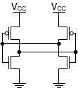
When Vcc = 0V, all values in the CMOS circuit are 0V and it's easy to determine the output (0V), however as the supply increases, it becomes impossible to know which side of the latch will be "HIGH" and which side will be "LOW" when the system reaches steady state without additional information. It's very easy for a latch like this to have different states on each successive startup.
Due to imperfections in manufacturing and system loading, it is possible for a latch to appear to start the same way every time, even when tested many times. It is important to note that this does _not_ guarantee that the output will _always_ be that value. Different devices can have different imperfections that can result in a different "default" output state, and this state can be changed by system loading. Lingering charge in a system very commonly will determine the state of a latch at startup.
--
I have found that it is possible to create a functional latch in SPICE, however the results are unreliable. What works in one simulator likely will not work in another, and even if a latch works perfectly, when combined with other circuit components, it often still results in convergence errors.
The best solution to create a latch is to use a simulator with a built-in system for handling digital logic. Most modern simulators include this capability, but they are not inter-operable. If, for example, we were to create a latched logic simulation that works with PSpice for TI, that same model would not be usable in any other simulator.
Because of these issues, we do not currently provide simulation models for latched logic.
--
What can you do if you can't simulate the device?
There are other options!
If you don't need to have the exact same functionality, but just need to check something like the output voltage or output current under certain conditions, you can find a non-latched device in the same logic family and use that SPICE model to check the output performance.
If you are looking to do signal integrity analysis, the best option is an IBIS model from the same logic family. IBIS models do not simulate functionality -- they only provide the output waveform of the device, and the majority of devices in the same logic family will have identical output drivers.
Finally, if you need to see how one of these devices works, you can get a few units along with an EVM and test them yourself in the real world. Remember that simulations are just mathematical models of the real world, and none are perfect. The absolute best way to verify that your design will work is to build a prototype and test it.