This thread has been locked.

If you have a related question, please click the "Ask a related question" button in the top right corner. The newly created question will be automatically linked to this question.

Linux/TXS0104E-Q1: Not work when VCCA connected to 3.3v & VCCB connected to +5v ,GND comman

Part Number: TXS0104E-Q1
Other Parts Discussed in Thread: PCF8575, LM1117

Tool/software: Linux

I am using TXS0104E-Q1 for I2C line please check bellow connections for reference.

I need to interface two I2C device 1. PCF8575(Supply voltage +5v)  2. SI7006(Supply voltage +3.3v)

1.PCF8575

when I connect Separate Source A with 3.3v and Source B with 5v and Ground common  Result : unable to read PCF8575.


when I connect Source A with 3.3v and Source B with 3.3v and Ground common  Result : Read successfully.


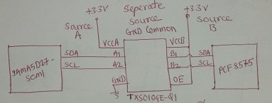
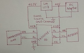
when I connect with same input source means DC adapter of 5v connected to VCCB and with the help LM1117 3.3v connected to VCCA  Result : unable to read PCF8575.


2.SI7006

when I connect Source A with 3.3v and Source B with 3.3v and Ground common  Result : Read successfully.


when I connect with same input source means 3.3v output of LM1117 connected to VCCB and VCCA  Result : unable to read SI7006.


After above experiment the conclusion is TXS0104E-Q1 is only work when apply separate source i.e. VCCA=VCCB=3.3v

Please help me to work with VCCA=3.3v and VCCB=5v with same source (GND common)


  • Hello, and welcome to the forums!
    The TXS0104E-Q1 is used in many systems worldwide with different supply voltages without any problems. I can say without any doubts that it functions fine with the supplies set to any valid value in the datasheet. 1.65 V to 3.6 V on A port and 2.3 V to 5.5 V on B; port (VCCA ≤ VCCB)

    I believe that there is an issue with communication in your system -- we will have to get some more information to determine what the problem is.

    Can you provide some details regarding your circuits?

    (1) How is the TXS0104E-Q1 connected to these devices? Are they all on the same circuit board? Are there any other devices on the bus?
    * This question is to help me determine the inductive/capacitive loading of the translator. larger than 70pF can cause problems with communication.

    (2) What is the input voltage, data rate, and direction of data flow when you are testing the communication?
    * It would be ideal if you can provide an oscilloscope shot of the input and output for at least one channel in each case so we can see what is happening to the signal.

    (3) Are there any external pull-up or pull-down resistors (or other components) connected to the communication lines? These could also be built in to the devices being connected to the TXS0104E-Q1.