This thread has been locked.

If you have a related question, please click the "Ask a related question" button in the top right corner. The newly created question will be automatically linked to this question.

SN74LVC1G07: Can we power the buffer with voltage divider from 12V and still operate properly?

Part Number: SN74LVC1G07
Other Parts Discussed in Thread: TL431

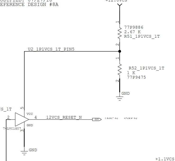
If the device is an open drain driver, would it be possible to use the buffer with a voltage divider for VCC?

Do you have a more comprehensive transistor level diagram I can look?

  • Hi,

    The resistor divider is a great way to do cheap down translation with passive components however it is not so great for powering a device. The buffer you are using is a CMOS device which consumes power from the Vcc pin to drive the outputs. Here is a simplified diagram of the internals of a CMOS gate.

    As you see, when the output needs to driven high, the top FET turns on, connecting the VCC pin to your load. At this point current will be drawn into the device from the Vcc pin. If current flows into the device from your fixed resistor divider, then a simple KCL or KVL on the node will tell you that the voltage will not stay fixed but will begin to vary. This will cause the supply voltage on the device to vary causing the output voltage to vary. This is not a desired operating condition and so the resistor divider will not work to power the device. If the current flowing into the device was fixed, then a resistor divider might have been possible.

    Thanks!

    -Karan

  • Hi Karan,

    For SN74LVC1G07, its an open drain buffer so I believe we don't have the P-fet on the CMOS configuration... do we?

    I agree with the above for the case of the SN74LVC1G17 which is an active driver.

  • All logic devices have lots of internal buffers. Only the output is open drain.

    If you do not have a supply voltage in the 1.8 V… 5 V range, you need a voltage regulator. (And even a cheap TL431 would need less current than that divider.)

    And the output (pin 4) must never see 12 V. (I'm mentioning this because the signal has a suspicious name.)

  • Yep that's what I thought. That's why I wanted to see if I could get a copy of how the transistors are set-up.

    Thank you!

  • Hi,

    Sorry, I did properly see the open drain part number. You can use a resistor divider in this case. I would use larger values, than the 1k to reduce the power you will drain using the divider.  

    I also agree with Clemens, applying 12V to the output will definitely damage the device so please make sure that is not the case.

    Thanks!

    -Karan