This thread has been locked.

If you have a related question, please click the "Ask a related question" button in the top right corner. The newly created question will be automatically linked to this question.

SN74LVC1G17: Undershoot of output waveform of SN74LVC1G17

Part Number: SN74LVC1G17
Other Parts Discussed in Thread: SN74AUC1G17

Hi team,

My customer is using our SN74LVC1G17 level shift to drive 12 channel SDI IC.

The schematic and the output waveform is as below.

They have used two kind of situation. The difference of them is using different condition of  open drain resistor (2), series resistor (1) and parallel cap (3) in the schematic.

First one: 1. series resistor=18ohm, 2. open drain resistor=500 ohm, 3. parallel capacitor=10pF

Result:  Worst rising time in 12 channel=8.402 ns

It is not allowed by next stage IC. The spec is only 5ns 

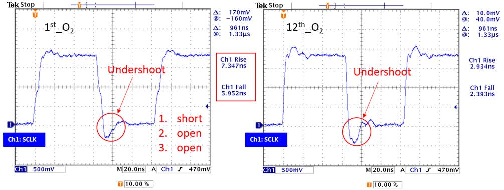
Second one: 1. series resistor=short, 2. open drain resistor=open, 3. parallel capacitor=open

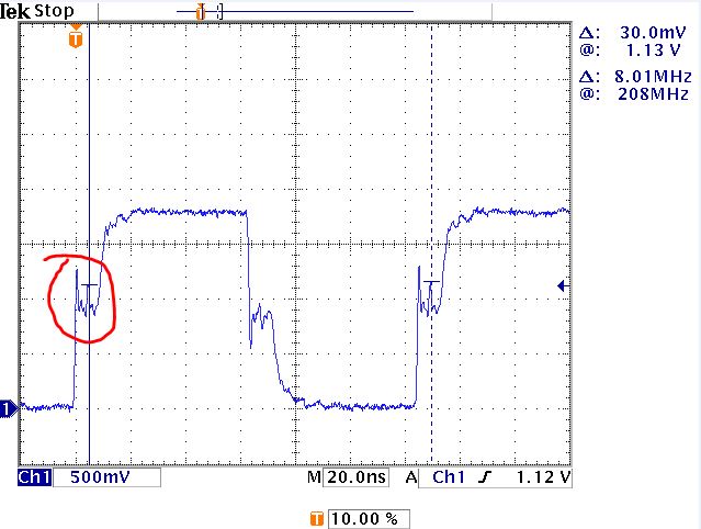
Result:   rising time has improved but it will have undershoot behavior 

May I have your help? How to improve the undershoot behavior ? Is it the measurement error or not? The input capacitance of probe is about 8pF. The trace between level shift  to SDI IC is about 8000mil.

  • The  SN74LVC1G17 does not have an open-drain output.

    The undershoot might or might not be a measurement error. Anyway, to reduce ringing, you should have a series resistor that (together with the buffer's output impedance) matches the trace's characteristic impedance. Alternatively, consider the SN74AUC1G17, which has output drivers that reduce line-reflection noise (see section 2.1 of Application of the Texas Instruments AUC Sub-1-V Little Logic Devices).

  • Hi Feng,

    As Clemens stated, it may or not be an error. However, based on the customer trying to increase transition speed, it doesn't surprise me that the undershoot would get worse.

    Clemens is spot on with the suggestions that should help you with this. Here is also an FAQ that covers this:

  • Hi Clemens & Dylan,

    Thank for your suggestion. Customer has  changed into  SN74AUC1G17 and improve the undershoot performance.

    But, there is one thing would like to consult with you about the rising time.

    Customer has used  probe P6139B which has 8pF input capacitance.

    The next stage of level shift is a SDI IC and it ask the rising time spec should be smaller than 5ns.

    From our measurement result , it will be higher than it. It will be 1xns at the worst result.

    There are two question about it.

    • Is it possible to quantify the rising time by our level shift?  It will only have 10ohm series resistor between level shift and sdi ic and our measurement point will be at sdi ic side.
    • Since there is 8 pF input capacitance of probe, it will influence the rising time of waveform. Is there any way to evaluate it? 

    Thank for your help.

  • AUC outputs should not need a series resistor; remove it.

    Can't you move the buffer near the end of the long trace?

    The probe's 8 pF will influence the rise time if it is a noticeable part of the overall capacitance. What is the capacitance of the trace, and of the SDI chip input?

  • Hi Clemens,

    May I know about the risk of AUC output with series resistor ?

    Because the SDI LED driver IC insist to have a series resistor at front end.

    As my understanding, the series resistor is for impedance matching and it will also influence driving capability.

    Whether I have misunderstood anything about it.

    I am not sure how much capacitance of the trace but the input capacitance of SDI IC would be 1pF for single channel.

    It will have 12 channel at load.

    Do you have suggested level shift for better driving capability?

  • The AUC output already does impedance matching (see the linked application note). The series resistor just increases the rise time.

    What is that SDI IC?

  • Hi Clemens,

    Thank for your help.

    It is led driver ic  and level shift is driving spi signal.

    Customer couldn't provide the whole datasheet due to NDA problem.


    It seems there is no other way to improve the slewing performance except changing the design.

    We have discussed about using clock buffer  such as http://www.ti.com/lit/ds/symlink/cdc3rl02.pdf

    Or implement multiple level shift for different channel but would like to consult with you.

    Which way do you suggest more?

  • I suspect that the AUC buffer without a series resistor and without the oscilloscope probe will work. But you'd have to use an active probe to confirm this.

  • Hi Clemens & Dylan,

    There is one question about AUC device. 

    We have measured the waveform of level shift side and find that it will have stop over behavior during rising and falling edge which is shown at red circle as below figure. Is it the characteristic of AUC logic? Is there any way to improve this behavior. 

  • Hi Feng,

    How long is the trace they are driving? This looks like the signal is having major reflection issues.

  • Hi Dylan,

    Thank for your looking at it.

    The longest channel trace will be about 10 inch.

    Would like to consult with you whether the three phase output feature will induce this happened?

    We also test the end of trace which is near the led driver. The waveform has been mitigate.


  • Hi Feng,

    I believe the length of the trace is the culprit here. This has to do with line reflections and is not how the device operates (the app note shows example waveforms)