This thread has been locked.

If you have a related question, please click the "Ask a related question" button in the top right corner. The newly created question will be automatically linked to this question.

SN74121 output level

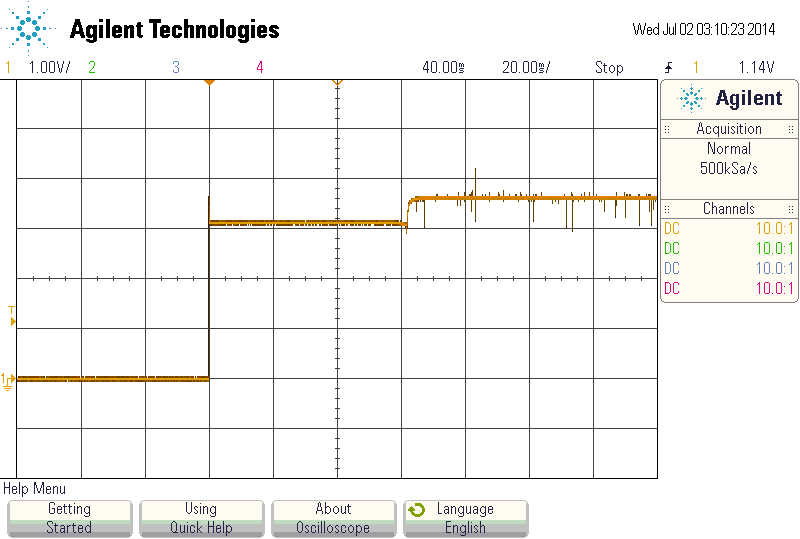
I am using SN74121D timer with its output loaded by SN74LVC2G32DCTR gate. The supply voltage for both ICs is 5 Volts. During a pulse generation, the timer output Q (pin 6) goes high but only to the level of 1.6 Volts. The circuit works as expected but I am wondering why the timer output is not even close to 5 Volt. The datasheet for SN74121D is very old and does not contain any example circuits.

I tested another SN74121D timer from a different lot. Even without a load its output goes high only to the level of 1.4 Volts. This is a suspiciously low voltage for a logical high level.

What is wrong?

Thank you.

  • A TI representative advised me to reply to myself in order to get someone's attention on the Logic Team to this post.

    I have not received any response to my Service Request# 1-1463759703 in a week :-(

  • I am attaching the schematic and the recordings of the waveforms that I get.

    Still waiting for a single reply from TI.


    7485.74121.pdf

    8132.TP1.txt
    ANALOG
    Ch 1 Scale 1.00V/, Pos 2.00000V, Coup DC, BW Limit Off, Inv Off, Imp 1M Ohm
         Probe 10.000 : 1, Skew 0.0s
    
    TRIGGER
    Sweep Mode Auto, Coup DC, Noise Rej Off, HF Rej Off, Holdoff 40.0ns
    Mode Edge, Source Ch 1, Slope Rising, Level 1.13750V
    
    HORIZONTAL
    Mode Normal, Ref Center, Main Scale 20.00ms/, Main Delay 40.000000000ms
    
    ACQUISITION
    Mode Normal, Realtime On, Vectors On, Persistence Off


    7752.TP2.txt
    ANALOG
    Ch 1 Scale 1.00V/, Pos 2.00000V, Coup DC, BW Limit Off, Inv Off, Imp 1M Ohm
         Probe 10.000 : 1, Skew 0.0s
    
    TRIGGER
    Sweep Mode Auto, Coup DC, Noise Rej Off, HF Rej Off, Holdoff 40.0ns
    Mode Edge, Source Ch 1, Slope Rising, Level 1.13750V
    
    HORIZONTAL
    Mode Normal, Ref Center, Main Scale 20.00ms/, Main Delay 40.000000000ms
    
    ACQUISITION
    Mode Normal, Realtime On, Vectors On, Persistence Off


  • The output should be greater than 1.6V. It should be about Vcc-1.  The ouput from the LVC part should be greater than 3.2V also.

    I dont see anything wrong on the schematic.  IC1B pin 6 is connectd to somthing right?

    I am not seeing anything right off that would cause the low output. Have you tried another part?

  • Chris, thank you for your reply.

    Yes, pin 6 is connected, and as I wrote before, "I tested another SN74121D timer from a different lot."

    I have assembled PC boards if you would like to take a look at one and do the testing yourself. Or maybe you could obtain a sample of this chip and reproduce what I see on a breadboard? I'd like to know that I am not crazy... yet :-)

  • Dear Chris,

    Is there anything being done at TI to help me with my case?

    Is there a modern datasheet for the 74121? Any application notes?

    Is anybody trying to reproduce what I see?

    Thanks,

    Sergey

  • Hi Sergey

    I have ordered some parts and I will see If i can duplicate the issue.

    These parts are old enough to where we did not have any in our sample stock. I ordered them from Digikey.

    Keep in mind that these parts are tested to Voh level of 3.4V before they go out the door.


  • Dear Chris, I have solved this problem. I was just typing the description below when your post came.

    There was an RC filter in the Vcc node (100 Ohm, 1 uF) right after the power entry connector.

    My fault - I got too much used to the supply current values of 10 uA or less in modern logic ICs - that I did not pay attention to the power consumption of 74121. It turns out that this prehistoric monster has the Icc rating of up to 40 mA!
    That is enough to cause a voltage drop of 4 Volts across a 100 Ohm resistor in the supply line. And that is what I've been observing.

    Mystery solved. Many thanks to everyone for their attention to this thread.

  • I need a 3.5 V VCC replacement for the 74121, dual input single output. Can anybody please assist.

  • Thank you for the reply Chris,

    However, these IC's also operate on 5V VCC and have one input and one "not" input.

    This forms part of a circuit based on a MSP430 and I would prefer not to create an extra 5V. It is an add on and I would like to keep the circuit as small and simple as possible. TI must surely have an equivalent able to do the same as the 121 with a 3.6V supply votage?

  • All of the three listed above can operate from about 2V to 5V Vcc. They do the same as the 121.

    they have 3 inputs with one of them inverted. and 2 ouputs with one of them inverted. ecxept for the 1G123 that has only 1 output..

      I am not sure which parameter you need that is not available on these.