This thread has been locked.

If you have a related question, please click the "Ask a related question" button in the top right corner. The newly created question will be automatically linked to this question.

SN74AHC1G125: negative glitch

Part Number: SN74AHC1G125
Other Parts Discussed in Thread: SN74LVC1G123

Hi,

The reset pulse will cause the input to go low briefly at the end of the pulse input.

what kind of protection circuits this device has. Normally the two diodes at the input protect the device.

the question is how much energy is needed to destroy these didoes.

The reset pulse is 3.3V and 100us duration.

Thank you

Siva

  • Hi Siva,

    Your image didn't come through, please repost if you need me to see.

    The AHC logic family only has negative clamp diodes on the input. If the input voltage is going negative more than 0.5V, then the current needs to be limited to 20mA maximum to avoid damage.

  • Hi Emrys,

    Thanks for the reply, see the image below.

    Siva

  • Hi Siva,

    I can only see what you see _after_ you post. If you copy/paste an image into the editing box it shows up, but then won't link properly when you click the "Post" button.


  • Hi Emrys,

    I have use the insert file method, hopefully you will get it.

    Regards

    Siva

  • Hi Siva,

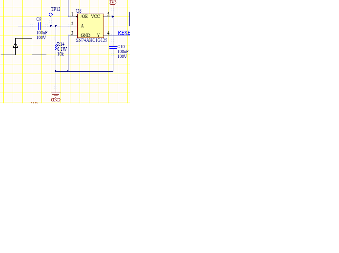
    Thanks for the schematic.

    I assume that the signal at the open end of C9 is a 3.3V square wave.

    The series capacitor will create a large negative voltage spike at every falling edge, which in turn will cause a large amount of current to flow through the protection diode.  I put together a quick simulation to show this.

    The first circuit has no protection diode, which just shows the voltage that the circuit "wants" to go to. In this case, it gets to about -3.3V, which is what we'd expect from a 3.3V input signal.

    The second circuit is what you have shown, with no limiting resistor. You can see from Id2 that the current exceeds the datasheet maximum rating of 20mA by a pretty large margin --  the simulation actually has a hard time with this because it's trying to drive infinite current here, and obviously that can't be done.

    The third circuit has a limiting resistor at the input (220 ohm), which reduces the diode current to a safe level (13mA) and results in pretty much the same waveform as the second circuit -- minus the huge current.

    There is one additional hidden problem in this circuit - you have created a slow input into a standard CMOS device. This will cause extra power consumption, reduction in lifetime of the device, and possibly oscillations at the output. There's more info on this here: [FAQ] How does a slow or floating input affect a CMOS device?

    I would recommend instead to use a rising edge detection monostable circuit such as the SN74LVC1G123 -- it will avoid all the issues associated with this circuit.