This thread has been locked.

If you have a related question, please click the "Ask a related question" button in the top right corner. The newly created question will be automatically linked to this question.

LSF0102: Schematic review

Part Number: LSF0102
Other Parts Discussed in Thread: SN65DSI83, SN74AUC1G125, TXS0102, LSF0101, LSF0108,

Hi,

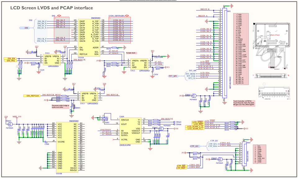
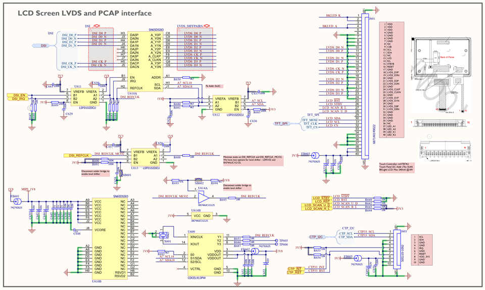
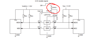
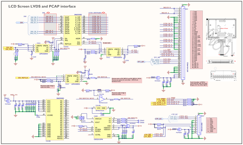
This is a follow-on question from this post (link) regarding a level shifter to use for a DSI REFCLK input to the SN65DSI83.

Could you please review schematic below and please let me know if I have connected the level shifter correctly

Thank you very much in advance

Kind regards

Navin

  • Hi,

    I just noticed myself that U613 pin 1 needs to connect to GND, apart from that would there be any other issues?

    Thanks
    Navin

  • Hi,

    I've made the correction (please check below)  and added the option of using SN74AUC1G125 as well. Using solder bridges, I can enable whichever level shifter I want. 

    Thanks
    Navin

  • Navin,

    I would recommend looking at the series of logic minute videos that I linked in the previous E2E thread on the LSF family to understand how to set this circuit up. Additionally the datasheet is a good reference. The bias circuit and the setup for down translation are missing some things here. 
    For instance, you'll need a resistor for the Vref_B pin. 200k should work. And you won't need the resistor such as R689 to connect the 3.3V supply on the high side to the EN pin. From the series, this video on the bias circuit should help.

    Additionally watching this specific video on down translation on the LSF should be useful as well. 
    You seem to be using push pull input down translating strictly in some instances such as the REFCLK. Is the leakage current less than 1uA on the input REFCLK? If not, you'll need a pull up resistor on the output. Watch the videos on up translation and down translation with the LSF family to make sure your setup is proper.

    I know it was mentioned in the linked thread that the clock source feeding into the REFLCK would be from 25MHz to 154MHz but how about the other I2C on U612, and clock references on U613?
    For U612 it wouldn't be a bad idea to replace this with a TXS0102 if the speed will accommodate this. It may be an easier part to work with. But the LSF will still work. 

     Rami

  • Hi Rami

    Thanks for pointing out the issue, and for the relevant links to the videos. I have made the correction as seen below.

    Re REFCLK U613: On the SN65DSI83 datasheet it says that max leakage current to all inputs is <30uA. I will add a 100R pull up resistor on the output of the U613. Assuming 10pF worst case parasitic capacitance, RC constant is 1ns. Input to U613 is push-pull.

    Re I2C U612: Max frequency is 400kHz and is open drain, I think I will change those pullups to 2K2 to give me a faster response.

    I was hoping that if I used LSF I can use it for all three functions and consolidate part numbers rather than have two separate ones, but we will see once the circuit is built. Please let me know if the below circuit is ok

    Thanking you very much in advance

    Kind regards

    Navin

  • Navin,

    For the most part, this looks good. The output of U612 would need a pull up as well unless the input on U609 is less than 1uA. 
    On U613, is the A2 -> B2  channel unused? You don't need to pull this up. It's a passive switch so you could leave it unconnected or downsize to the LSF0101. 
    You do have 3 LSF0102's here all down translating from 3V3 to 1V8. Maybe this is better for testing purposes but if you're aiming to consolidate and the LSF is what you end up using over the AUC, there is an LSF0108 that would have 8 channels so just a single chip could do all this for you.

    Thanks,
    Rami 

  • Hi Rami

    Thanks for your review.

    Outputs of U612 have pullups connected (R680,R681) and they are open drain (I2C). U613 A2-B2 channel is unused, I will remove that resistor. Thanks for that information, I wasn't sure whether I could leave that floating or not. I think it would be better to stick with LSF0102s as the LSF0108 has a bit longer propagation delay. Also this way I can be more flexible with component placement and reduce unnecessary stubs.

    Thanks for your assistance, much appreciated

    Kind regards

    Navin