This thread has been locked.

If you have a related question, please click the "Ask a related question" button in the top right corner. The newly created question will be automatically linked to this question.

Bricked CC-Debugger - led lights ORANGE.Updated - solution found!

Other Parts Discussed in Thread: CC-DEBUGGER, CC2511

Dear Sirs,

Any ideas what went wrong with my CC Debugger: I was working with CC1110-DK Mini board attached. At some point IAR said about the problem with driver and then hanged. I've looked at debugger's led - it became yellow (orange): both green & red leds were on. Now I can't see the debugger neither from HW Manager on my PC (I've tried 2 PCs) nor in software like RF Studio & IAR. I think this may be firmware failure but attempt of starting bootloader by shortening P1.6 to GND failed - it still lights amber. Pressing RESET button cause the led is OFF while the button is pressed.

Any ideas how to de-brick it?

Regards,

Ilia V. Davidov

[UPDATED] I've solved this problem - see my later posts here.

  • Dear Ilia,

    It sounds like you have erased the CC Debuggers flash memory - this will cause the CC Debugger LED to be amber. You should be able to ressurect the failing CC Debugger using a second CC Debugger or a SmartRF05EB. You can find the details of this procedure in section 8.4 of swru197.

    Regards,

    ABO

    --
    PS. Thank you for clicking  Verify Answer  if this answered your question!

  • I've successfully restored my CC-DEBUGGER without buying second one :) Because buying of the new one for flashing the old one - it's something like PKUNZIP.ZIP :)

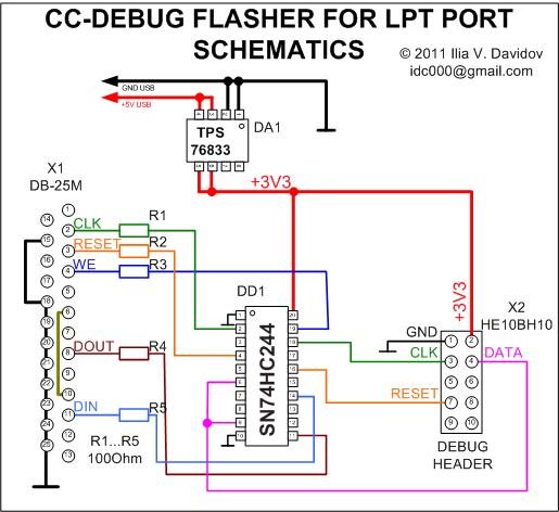
    Simple schematics using only two relatively cheap IC's, LPT port, USB for power supply - and now my CC-DEBUGGER is alive. If you want to follow my steps, please take a look at attached schematics, also you'll need usb bootloader firmware for CC-Debugger , which is available in RF Studio, in binary (not HEX) format (attached here:   4130.usbboot.zip ) and software flasher for LPT port I'll publish ASAP here which will allow you to flash your CC-DEBUGGER

    .

    My software is now at pre-alpha "quick&dirty" stage, but if you need is urgently, please feel free to contact me.

    Software can be found here. 

    Regards,

    Ilia V. Davidov

     P.S. BTW, as debug protocol is public ( swra124.pdf ), it's possible to implement full-featured flasher/debugger for CCxxxx transceivers for LPT port, (in this case CC-DEBUGGER becomes useless at all :) ), but a lot of ready to use software solutions like RF Studio etc. will also become unusable :( as these programs don't recognize this LPT debugger.


  • hi, Ilia. I have build a parport programmer too, and program the usb bootloader to cc2511, i think the program process is successful, because i read out the flash and it's same with the data I write to. and the read led blink(at different frequency when i connect P1.6 to GND or not)

    But windows report the debugger as Unknown deive with vid and pid all 0000H, it seems the usb doesn't work

    I don;t know what's wrong. what is your cc debugger's red led behavior? thanks

  • Hi!

    Just after flashing with my programmer my CC-Debugger started as noted in it's manual - the red led was blinking (after attaching to usb), then Windows found it as CC-Debugger (USB\VID_0451&PID_16A2\00000170). In your case it looks like you have a problem with bootloader, especially with bytes from offset 0x9B, it should be 0x51 0x04 0xA2 0x16 - VID (0451) and PID(16A2) constants for USB. So to check you flash your cc2511 correctly, try to program my usbboot.bin attached to my previous post. After this read it back - to verify. Also please check the voltage of power supply of CC-Debugger (it should be +3.3V, as in my case due to damaged LDO it was +2.9V).

    Hope this will help you.

    If your LPT-pinout is the same as mine, you may try my version of flasher - inform me, this will reinforce me to finish this project :)

    Regards,

    Ilia

    p.s. hope you convert HEX to BIN correctly... to check this just compare your file with mine one. Also check your D+, D- pinout, schematics,board routing (if it's selfmade) and USB cable.

    p.p.s. If you find my post useful please click "Verify Answer" button.

  • Hi!

    the usbboot.bin i used is same with you, except i add oxff at the end of the file to make the file size reach 6K byte(to make my rough programer happy). I have verify the flash content after write to it, it seems ok.

    the vid pid are 0000, it's nothing different as you pull the D+ to 3.3V through 1.5K resistor. I think the problem related to my pcb layout, the trace is really long, about 10cm, connect to a usb hub chip and then to PC usb port. I am not sure cc2511's usb can work with this layout(but other usb chip works on the board, its trace is even longer). it seems i need to debug my board

    my lpt pinout is different with yours

  • Hi,

    I agree with you - it looks like a HW problem of your board. To make sure your cc2511 is OK, you may try to connect it to your PC directly, without USB HUB IC (just cut-off wires D+, D- and solder them (&GND ) directly to USB connector. Also check the power - may be it's not enough.

    Regards,

    Ilia

  • Hello,

    I have the same problem: the led on debugger lights up orange/yellow.

    Are there any news to solve the problem? Or is the way to repair the debugger still like mentioned in this thread here?

    If yes, there are two possibilities: Either buy another debugger or use the way Ilia described. Correct?

    Thanks!

  • If you've bricked you CC Debugger by corrupting the bootloader, the only way to resurrect it is to re-program it using another programmer. Since your CC Debugger LED is amber, it does unfortunately sound like this is the case.

    Edit: To program the bricked device, you can use SmartRF05EB, another CC Debugger or a custom programmer like Ilia Davidov's

    Br,
    ABO 

  • Okay, thank you for the information!


    Now i have a second CC Debugger and would like to resurrect the bricked CC Debugger.

    First of all, I updated the firmware of the new CC Debugger. I used SmartRF Studio 7 to update the firmware, it's now "Firmware revision 0025".


    Well, here is the problem:

    I use the CC Debugger User's Guide (swru197c.pdf). In section 8.4, there's only a picture of the connection from a SmartRF05EB to the bricked CC Debugger. It does not explain how to connect another CC Debugger.

    Which way I have to connect the 10-pin flat cable at the bricked CC Debugger? The nose, which avoid wrong polarisation can't used, cause there's no receptacle.

    Does the nose of the cable have to point to the center of the bricked board or to the edge of the bricked board?


    I hope you know what I mean. Sorry, my english is not that good.


    Edit: Unfortunately, I did not recognize that the cable itself shows the correct connection: Simply pay attention to the red marked line on the cable! :)

  • Hi,

    On the debug connector on the bricked CC debugger, pin 1 is marked with a small arrow/triangle (indicated below). You should connect the red part of the 10-pin flat cable to this pin.

    Br,

    ABO

  • hi Ilia, my name is Emanuel. What is the software used to flash the cc debugger for the LPT port?.

    Thanks for your help and sorry, my english is not that good.

  • Hi Emanuel,

    I've wrote  my own software for programmer I've posted above. It's still at pre-alpha stage as I've suspended this project after I restored my CC-Debugger. If you need this software, just let me know - I'll try to finish it and share it to community. But as I'm too busy now, I need about a week to do this.

    Regards,

    Ilia 

  • Hi Ilya,

    I need to restore my CC-Debbuger. If you could load the software would be helpful. Thank you very much.

  • Hi Emanuel,

    Will try to finish project during weekend.

    Ilia 

  • Hi Ilia,

    Thank you very much.

    Emanuel

  • 5850.CCRESCUE.rar

    Dear Sirs,

    Let me introduce the first version of my CC-Rescue software for the LPT-programmer, described above. This software will help you if you have bricked CC-Debugger with ORANGE LED, which can't be restored via USB bootloader (as described in swru197 document).

    Prior to use this software please note that:

    a) It's tested only on Windows XP. Both Windows 7 & Vista are not supported.

    b) Only hardware LPT ports in Standard or EPP mode are supported. This software will never work with USB-to-LPT adapters, sorry.

    c) Use this software only as a LAST HOPE solution to resurrect your CC-Debugger.

    d) You may use this product AS IS, with no warranties at all. Also Borland Delphi 7 sources are included - so you may freely upgrade it (please refer to me in your builds) . 

    HOW TO:

    1) Make my LPT programmer as described in this topic, download RAR archive, attached to this post, unrar it to any folder. 

    2) Connect programmer to your damaged CC-Debugger via internal debug port of CC-Debugger. Prior to this step please check that your CC-Debugger's hardware (incl. LDO 3V3 source) is OK. Also check that your CC-Debugger is not connected to USB port, the only one connection should be made between PC and CC-Debugger: using LPT port & my device. CC-Debugger will get power from my device.

    3) Connect programmer to LPT port and than to USB (to switch power on).

    4)  Start CCRescue.exe

    5)  Now, first of all, check LPT's base address. It's set to 0x378 by default.

    6) Press "1.  GET CHIP ID"

    7) Take a look at log window. There should be a message that CC-Debugger is found. If not - re-check everything.

    8) Now try to make a backup copy of CC2511 flash - press "2. BACKUP CC-Debugger", please wait (about a minute, it looks like it hangs, but it's OK). Now specify filename to save backup image to.

    9) Now you are ready to try to rescue CC-Debugger. Press "..." button near the filename field. In the dialog please select new firmware binary image. You may flash SRF05DBG.BIN (from "firmware" folder of archive) - it's a usb bootloader, that will allow you to make your CC-Debuger flashing RED LED, and than restore it as described in swru197. The alternative way is to use "full-backup.bin" - it's a full backup of working CC-Debugger (not only USB bootloader).

    NOW YOU ARE READY TO PRESS "3.  FLASH CC-Debugger" BUTTON! JUST DO IT!

    Wait until flash process is finished. Now detach your CC-Debugger from programmer and try to connect it to PC via USB. It should work. (LED should be RED or BLINKING RED, depending on firmware you're selected).

    GOOD LUCK!

    Regards,

    Ilia V. Davidov