This thread has been locked.

If you have a related question, please click the "Ask a related question" button in the top right corner. The newly created question will be automatically linked to this question.

Is there sample code to program the GPIO on SmartRF

Other Parts Discussed in Thread: CC2540

Hi, all.

   First I want to thank everyone who helped me before.

   I have a new question.

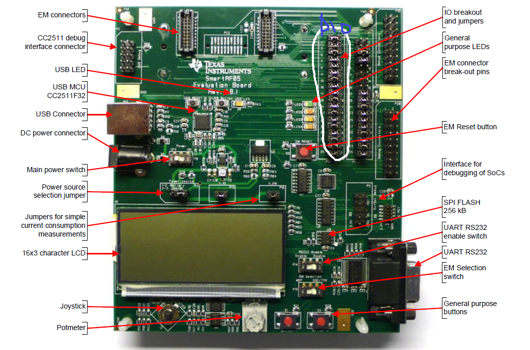
   I want to program the GPIO on SmarRF board to send signal to other devices. I planned to use the P20 jumpers. Is there any sample code that I can follow to make them as output and set the values that I want set for each pin?

  Thanks very much.

  • GPIO is easy ;)

    Check the datasheet. I will give you an example for port 0.

    First, you have to set the pin's function (P0SEL0 = GPIO) next, the pin's direction (P0DIR = 0xFF for outputs) and then, oyu can play with the value you want P0 |= BIT6 is going to output a 1 through P0.6

    :)

    Have a nice day!

  • ... and don't forget: P0 &= ~BIT6 will output a 0 on P0.6!

    :)

  • Thanks. I am very new to hardware programming. Can you show the sample c code for the above logic.

  • I've just done!

    Check the simpleBLEPeripheral project!

    :)

  • Sorry if I sound stupid, but can you point me to which exact file and what lines? Really appreciate your help.

    I have been modifying the SimpleBLEPeripheral project, but I didn't see the sample code for how to program the jumper.

  • Hi, I think I know what you mean now.

    but I have a problem. P0SEL was defined in IAR include files, but i didn't find P10SEL defined anywhere which are the GPIO i want to use. Any idea how to solve this problem? Thanks.

  • Come on, read the datasheet, the answer is easy.

    P10SEL does not exist. It is common to do such mistypings :)

    http://www.ti.com/lit/ug/swru191c/swru191c.pdf

    Bye!

    Good luck!

    And verify the thread in order to keep the forum clean. Thanks!

  • Hi,

       Again, I appreciate the help. As you might have noticed, I have very little to 0 EE experience. So please be patient with me, as something might seem really easy or obvious to you, it might be something that doesn't make sense to me at all. 

       With that been said, I have tried to look at the datasheet, but it seems very foreign to me. I can tell  you what I want to do. On my SmartRF05 board, there is p10, show in the picture. 

    I want to connect some of the pins from p10 to some relays, and programmatically to turn on the relay on and off. As you have mentioned, there is only P0, P1, P2. Where are they on the board? Can you point them to me? I am very confused here. Thanks very much.

  • Hi,

    Looking at the SmartRF05EB schematics (swru210) will probably be a very good exercise for you. If you are new to embedded programming, you might as well start understanding schematics right away :)

    In the user's guide, of the SmartRF05EB, you'll find the schematics for the SmartRF05EB in the Appendix section. Now, if you are connecting e.g. a CC2540EM to the SmartRF05EB EM connectors, you'll need schematics for the CC2540EM as well (located in the reference design zip file).

    Now, trace the signal going from header P10 on SmartRF05EB to the EM connector and then from the EM connector on the CC2540EM to the CC2540 chip.

    For example:

    1. 05EB schematics, Top level page: Signal going from header P10, pin 1 to the EM connectors is called EM_JOY_MOVE.
    2. 05EB schematis, EM interface page: EM_JOY_MOVE is connected to EM connector P6.19 (the "right side" connector).
    3. CC2540EM schematics: The corresponding pin on the "right side" connector (P2.19) is connected to CC2540 P2.0

    So, header P10.1 on SmartRF05EB is connected to P2.0 of CC2540 on the CC2540EM.

    To configure CC2540 P2.0 as GPIO output, logic 1:

    P2SEL &= ~0x01; // Setting bit 0 of P2SEL to 0 (setting P2.0 as GPIO pin)
    P2DIR |= 0x01; // Setting bit 0 of P2DIR to 1 ( setting P2.0 as output)
    P2 |= 0x01; // Setting bit 0 of P2 to 1 (since P2.0 is gpio output, this will set the pin to logic 1)

    More information about the CC2540 GPIO pins can be found in section 7 of the CC2540 user's guide (swru191).

    Hope this helps!

    Br,
    ABO

    --
    PS. Thank you for clicking  Verify Answer  below if this answered your question!

  • Hi, TIABO,

       Thanks very much. That was very helpful. I was able to figure out all the mapping following your lead. And I was able to detect the voltage to be 0.2. Is there a setting that I need to set to make the voltage to 3.3v?

  • Xin,

    I see you've started a new, but related thread, http://e2e.ti.com/support/low_power_rf/f/538/t/201706.aspx, let's continue the discussion there :)

    Br,
    ABO