This thread has been locked.

If you have a related question, please click the "Ask a related question" button in the top right corner. The newly created question will be automatically linked to this question.

LAUNCHXL-TMS57004: Error connecting to the target:(Error -183 @ 0x0)

Part Number: LAUNCHXL-TMS57004
Other Parts Discussed in Thread: UNIFLASH,

Hello!

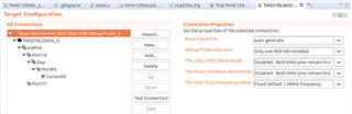
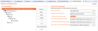
I am using a TMS570LS043x board with a XDS100vw jtag connection and I am having this problem when I try the test connection.

The log is above:

[Start: Texas Instruments XDS100v2 USB Debug Probe]

Execute the command:

%ccs_base%/common/uscif/dbgjtag -f %boarddatafile% -rv -o -F inform,logfile=yes -S pathlength -S integrity

[Result]


-----[Print the board config pathname(s)]------------------------------------

C:\Users\TAMIRE~1.BER\AppData\Local\TEXASI~1\
CCS\ccs1040\0\0\BrdDat\testBoard.dat

-----[Print the reset-command software log-file]-----------------------------

This utility has selected a 100- or 510-class product.
This utility will load the adapter 'jioserdesusb.dll'.
The library build date was 'Jun 25 2021'.
The library build time was '11:45:30'.
The library package version is '9.4.0.00129'.
The library component version is '35.35.0.0'.
The controller does not use a programmable FPGA.
The controller has a version number of '4' (0x00000004).
The controller has an insertion length of '0' (0x00000000).
This utility will attempt to reset the controller.
This utility has successfully reset the controller.

-----[Print the reset-command hardware log-file]-----------------------------

The scan-path will be reset by toggling the JTAG TRST signal.
The controller is the FTDI FT2232 with USB interface.
The link from controller to target is direct (without cable).
The software is configured for FTDI FT2232 features.
The controller cannot monitor the value on the EMU[0] pin.
The controller cannot monitor the value on the EMU[1] pin.
The controller cannot control the timing on output pins.
The controller cannot control the timing on input pins.
The scan-path link-delay has been set to exactly '0' (0x0000).

-----[The log-file for the JTAG TCLK output generated from the PLL]----------

There is no hardware for programming the JTAG TCLK frequency.

-----[Measure the source and frequency of the final JTAG TCLKR input]--------

There is no hardware for measuring the JTAG TCLK frequency.

-----[Perform the standard path-length test on the JTAG IR and DR]-----------

This path-length test uses blocks of 64 32-bit words.

The JTAG IR instruction path-length was not recorded.

-----[Perform the Integrity scan-test on the JTAG IR]------------------------

This test will use blocks of 64 32-bit words.
This test will be applied just once.

Do a test using 0xFFFFFFFF.
Scan tests: 1, skipped: 0, failed: 0

-----[An error has occurred and this utility has aborted]--------------------

This error is generated by TI's USCIF driver or utilities.

The value is '-183' (0xffffff49).
The title is 'SC_ERR_CTL_CBL_BREAK_FAR'.

The explanation is:
The controller has detected a cable break far-from itself.
The user must connect the cable/pod to the target.

[End: Texas Instruments XDS100v2 USB Debug Probe]

I tried to change the cable and also the seeting for the file ccxml are correct for the right board.

Could anyone know what is it? 

  • Also, the message when degub is that:

    Error connecting to the target:
    (Error -183 @ 0x0)
    The controller has detected a cable break far-from itself.
    The user must connect the cable/pod to the target.
    (Emulation package 9.4.0.00129)

    And my board is recognized in the device manager normally.

    Cant imagine what it is

  • Please take a look at this JTAG debug page:

    https://software-dl.ti.com/ccs/esd/documents/ccs_debugging_jtag_connectivity_issues.html

    Is the board powered properly (1.2V, 3.3V)? 

    The FAQ and troubleshooting in the following doc may help you:

    https://software-dl.ti.com/ccs/esd/documents/xdsdebugprobes/files/XDS100.pdf

  • Hi

    I saw the page of JTAG debug but could not find anything that applies.

    Yes, the board is powered properly and It is on, also recognized by the UNIFLASH for example...but the communication is failing with this error.

    Also read the FAQ for XDS100 already but dont know what to do...they say coud be a wrong connection between TDIS and GND...but I cant understand how to fix it. Can you be more specific about it? Maybe is that the solution...

    Thanks!

  • Also read the FAQ for XDS100 already but dont know what to do...they say coud be a wrong connection between TDIS and GND...but I cant understand how to fix it. Can you be more specific about it?

    On a LAUNCHXL-TMS57004 using the built-in XDS100v2 there are no jumper or switch settings to control the connection to TDIS.

    On a Linux PC I have a FTDI usb-to-serial adaptor connected as well as a LAUNCHXL-TMS57004.

    The CCS 10.4 xds100serial utility reports the FTDI usb-to-serial adaptor as well as the XDS100v2 on the launchpad:

    $ ~/ti/ccs1011/ccs/ccs_base/common/uscif/xds100serial 
    Scanning for XDS100 emulators...
    
    VID/PID    Type            Serial #    Description
    0403/6010  generic FT2232  FTVIZUNN    FT2232H device 
    0403/a6d0  XDS100v1/v2     TIV9J7S0    Texas Instruments Inc.XDS100 Ver 2.


    In CCS 10.4 if attempt a test connection with the CCS Target Configuration set to the default Debug Probe Selection of "Only one XDS100 installed":

    Then the test connection fails with the same error as your case:

    [Start: Texas Instruments XDS100v2 USB Debug Probe_0]
    
    Execute the command:
    
    %ccs_base%/common/uscif/dbgjtag -f %boarddatafile% -rv -o -F inform,logfile=yes -S pathlength -S integrity
    
    [Result]
    
    
    -----[Print the board config pathname(s)]------------------------------------
    
    /home/mr_halfword/.ti/ccs1040/0/0/BrdDat/
        testBoard.dat
    
    -----[Print the reset-command software log-file]-----------------------------
    
    This utility has selected a 100- or 510-class product.
    This utility will load the adapter 'libjioserdesusb.so'.
    The library build date was 'Jun 25 2021'.
    The library build time was '11:41:54'.
    The library package version is '9.4.0.00129'.
    The library component version is '35.35.0.0'.
    The controller does not use a programmable FPGA.
    The controller has a version number of '4' (0x00000004).
    The controller has an insertion length of '0' (0x00000000).
    This utility will attempt to reset the controller.
    This utility has successfully reset the controller.
    
    -----[Print the reset-command hardware log-file]-----------------------------
    
    The scan-path will be reset by toggling the JTAG TRST signal.
    The controller is the FTDI FT2232 with USB interface.
    The link from controller to target is direct (without cable).
    The software is configured for FTDI FT2232 features.
    The controller cannot monitor the value on the EMU[0] pin.
    The controller cannot monitor the value on the EMU[1] pin.
    The controller cannot control the timing on output pins.
    The controller cannot control the timing on input pins.
    The scan-path link-delay has been set to exactly '0' (0x0000).
    
    -----[The log-file for the JTAG TCLK output generated from the PLL]----------
    
    There is no hardware for programming the JTAG TCLK frequency.
    
    -----[Measure the source and frequency of the final JTAG TCLKR input]--------
    
    There is no hardware for measuring the JTAG TCLK frequency.
    
    -----[Perform the standard path-length test on the JTAG IR and DR]-----------
    
    This path-length test uses blocks of 64 32-bit words.
    
    The JTAG IR instruction path-length was not recorded.
    
    -----[Perform the Integrity scan-test on the JTAG IR]------------------------
    
    This test will use blocks of 64 32-bit words.
    This test will be applied just once.
    
    Do a test using 0xFFFFFFFF.
    Scan tests: 1, skipped: 0, failed: 0
    
    -----[An error has occurred and this utility has aborted]--------------------
    
    This error is generated by TI's USCIF driver or utilities.
    
    The value is '-183' (0xffffff49).
    The title is 'SC_ERR_CTL_CBL_BREAK_FAR'.
    
    The explanation is:
    The controller has detected a cable break far-from itself.
    The user must connect the cable/pod to the target.
    
    [End: Texas Instruments XDS100v2 USB Debug Probe_0]
    

    Where the error occurs because CCS has attempted to use the FTDI usb-to-serial adaptor rather than the XDS100v2 on the actual LAUNCHXL-TMS57004.

    If the CCS Target Configuration Debug Probe Selection is changed to "Select by serial number" with the Serial Number set to that reported by xds100serial:

    Then the test connection is successful:

    [Start: Texas Instruments XDS100v2 USB Debug Probe_0]
    
    Execute the command:
    
    %ccs_base%/common/uscif/dbgjtag -f %boarddatafile% -rv -o -F inform,logfile=yes -S pathlength -S integrity
    
    [Result]
    
    
    -----[Print the board config pathname(s)]------------------------------------
    
    /home/mr_halfword/.ti/ccs1040/0/0/BrdDat/
        testBoard.dat
    
    -----[Print the reset-command software log-file]-----------------------------
    
    This utility has selected a 100- or 510-class product.
    This utility will load the adapter 'libjioserdesusb.so'.
    The library build date was 'Jun 25 2021'.
    The library build time was '11:41:54'.
    The library package version is '9.4.0.00129'.
    The library component version is '35.35.0.0'.
    The controller does not use a programmable FPGA.
    The controller has a version number of '4' (0x00000004).
    The controller has an insertion length of '0' (0x00000000).
    This utility will attempt to reset the controller.
    This utility has successfully reset the controller.
    
    -----[Print the reset-command hardware log-file]-----------------------------
    
    The scan-path will be reset by toggling the JTAG TRST signal.
    The controller is the FTDI FT2232 with USB interface.
    The link from controller to target is direct (without cable).
    The software is configured for FTDI FT2232 features.
    The controller cannot monitor the value on the EMU[0] pin.
    The controller cannot monitor the value on the EMU[1] pin.
    The controller cannot control the timing on output pins.
    The controller cannot control the timing on input pins.
    The scan-path link-delay has been set to exactly '0' (0x0000).
    
    -----[The log-file for the JTAG TCLK output generated from the PLL]----------
    
    There is no hardware for programming the JTAG TCLK frequency.
    
    -----[Measure the source and frequency of the final JTAG TCLKR input]--------
    
    There is no hardware for measuring the JTAG TCLK frequency.
    
    -----[Perform the standard path-length test on the JTAG IR and DR]-----------
    
    This path-length test uses blocks of 64 32-bit words.
    
    The test for the JTAG IR instruction path-length succeeded.
    The JTAG IR instruction path-length is 6 bits.
    
    The test for the JTAG DR bypass path-length succeeded.
    The JTAG DR bypass path-length is 1 bits.
    
    -----[Perform the Integrity scan-test on the JTAG IR]------------------------
    
    This test will use blocks of 64 32-bit words.
    This test will be applied just once.
    
    Do a test using 0xFFFFFFFF.
    Scan tests: 1, skipped: 0, failed: 0
    Do a test using 0x00000000.
    Scan tests: 2, skipped: 0, failed: 0
    Do a test using 0xFE03E0E2.
    Scan tests: 3, skipped: 0, failed: 0
    Do a test using 0x01FC1F1D.
    Scan tests: 4, skipped: 0, failed: 0
    Do a test using 0x5533CCAA.
    Scan tests: 5, skipped: 0, failed: 0
    Do a test using 0xAACC3355.
    Scan tests: 6, skipped: 0, failed: 0
    All of the values were scanned correctly.
    
    The JTAG IR Integrity scan-test has succeeded.
    
    -----[Perform the Integrity scan-test on the JTAG DR]------------------------
    
    This test will use blocks of 64 32-bit words.
    This test will be applied just once.
    
    Do a test using 0xFFFFFFFF.
    Scan tests: 1, skipped: 0, failed: 0
    Do a test using 0x00000000.
    Scan tests: 2, skipped: 0, failed: 0
    Do a test using 0xFE03E0E2.
    Scan tests: 3, skipped: 0, failed: 0
    Do a test using 0x01FC1F1D.
    Scan tests: 4, skipped: 0, failed: 0
    Do a test using 0x5533CCAA.
    Scan tests: 5, skipped: 0, failed: 0
    Do a test using 0xAACC3355.
    Scan tests: 6, skipped: 0, failed: 0
    All of the values were scanned correctly.
    
    The JTAG DR Integrity scan-test has succeeded.
    
    [End: Texas Instruments XDS100v2 USB Debug Probe_0]
    

    Can you run the <ccs_install_root>\ccs\ccs_base\common\uscif\xds100serial.exe utility and see if more than one "XDS100 emulator" is reported, in case your PC has any generic FTDI usb-to-serial adaptors installed in case CCS is attempting to use something other than the XDS100v2.

    If xds100serial.exe reports more than one "XDS100 emulator" try changing the CCS Target Configuration to select the XDS100 by serial number.