This thread has been locked.

If you have a related question, please click the "Ask a related question" button in the top right corner. The newly created question will be automatically linked to this question.

TM4C1290NCPDT: SSI communication

Part Number: TM4C1290NCPDT
Other Parts Discussed in Thread: EK-TM4C1294XL

Hi,

I am using TM4C1290NCPDT customized board. EEPROM read/write not working using SSI2 for communication.

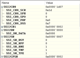
SSI2DR always showing 0 in register window? 

After SSIDataPut execution no change in SSI2DR register

SSIDataPut(SSI2_BASE, ucData);

while( MAP_SSIBusy(SSI2_BASE))
{
}

similarly SSIDataGetNonBlocking execution no change in SSI2DR register

if(SSIDataGetNonBlocking(SSI2_BASE, &uData))
{
*bptrReturnValue = (BYTE)(uData);

}

Kindly help.

Thanks.

  • Hello Thalapushpam,

    I am assuming this is an external EEPROM that you are communicating with?

    Did you have this working on an EVM like EK-TM4C1294XL before?

    Can you post your configuration code for the SSI2 module?

    Best way to post code is explained here: https://e2e.ti.com/support/site-support-group/site-support/f/site-support-forum/812271/faq-how-do-i-add-a-code-snippet-to-my-post

    Best Regards,

    Ralph Jacobi

  • Hi Ralph,

    yes External EEPROM(M95040) we are using in our application.

    Before received customized board We used EK-TM4C1294XL but not tested EEPROM read/write.

    Chip select we are controlling in software code, is it cause any issue?

    Others Tx,Rx,clk using TI's buildin.

  • Hello Thalapushpam,

    Chip select we are controlling in software code, is it cause any issue?

    No issue, this is what we typically do as well.

    If the EEPROM is untested, my first thought is to check the datasheet for what SPI mode needs to be used. There are different polarities and phases that can be used. One of the most common reasons for an issue with SPI on initial communication is having the wrong SPI mode selected.

    https://en.wikipedia.org/wiki/Serial_Peripheral_Interface#Clock_polarity_and_phase

    Best Regards,

    Ralph Jacobi

  • Ralph Thanks.

    As per EEPROM datasheet,

    Mode 0 only I am using in code, anyway if I put the data it will be able to view in DATA register right?.

    void SSCHardwareInit( void )
    {
      
      UINT32 ui32SysClock;
      
        // The SSI2 peripheral must be enabled for use    
        MAP_SysCtlPeripheralEnable(SYSCTL_PERIPH_SSI2);
        
        
        //SSI2 is used with PortD[0:3]
        MAP_SysCtlPeripheralEnable(SYSCTL_PERIPH_GPIOD);
        
        // Configure the pin muxing for SSI2 functions on PD[0:3]
        MAP_GPIOPinConfigure(GPIO_PD3_SSI2CLK);
       // MAP_GPIOPinConfigure(GPIO_PD2_SSI2FSS);
        MAP_GPIOPinConfigure(GPIO_PD1_SSI2XDAT0);
        MAP_GPIOPinConfigure(GPIO_PD0_SSI2XDAT1);
        
        // Configure the GPIO settings for the SSI pins
        // The pins are assigned as follows:
        //      SSI2
        //      PD0 - SSI2RX
        //      PD1 - SSI2TX
        //      PD2 - SSI2Fss
        //      PD3 - SSI2CLK
        MAP_GPIOPinTypeSSI(GPIO_PORTD_BASE, GPIO_PIN_3 |
                       /*GPIO_PIN_2 |*/ GPIO_PIN_1 | GPIO_PIN_0);
        
        //get system clock frequency
        ui32SysClock = GetSystemClockFrequency(); 
        
        // Configure and enable the SSI2 port for SPI master mode.  Use SSI2,
        // system clock supply, idle clock level low and active low clock in legacy
        // Freescale SPI mode Moto fmt, polarity 0, phase 0, master mode, 
        // 2MHz SSI frequency, and 8-bit data.
        // previously used 1MHz 2MHz used here needs to check
        MAP_SSIConfigSetExpClk(SSI2_BASE, ui32SysClock, SSI_FRF_MOTO_MODE_0,
                           SSI_MODE_MASTER, 2000000, 8);  


        // Enable the SSI2 module
        MAP_SSIEnable(SSI2_BASE);  
        
        
        GPIOPinWrite(GPIO_PORTH_BASE, GPIO_PIN_0, 1);     
    
    }

  • Hello Thalapushpam,

    The configuration code here all looks fine to me, have you scoped the SSI lines to see how the data looks?

    I think at this point you will need to verify the commands and such with an oscilloscope or LSA to make sure the EEPROM is receiving the right commands. If you see anything unusual with the TM4C output, then definitely share the screenshot so I can see what is going.

    But based on your description of the requirements for the EEPROM and your configuration code, I wouldn't expect any issues with the SSI itself.

    Best Regards,

    Ralph Jacobi