This thread has been locked.

If you have a related question, please click the "Ask a related question" button in the top right corner. The newly created question will be automatically linked to this question.

TMS570LC4357: JTAG programming issue with XDS200 for TMS5704357BZWTQQ1 Microcontroller

Part Number: TMS570LC4357
Other Parts Discussed in Thread: LAUNCHXL2-570LC43, UNIFLASH

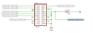
We have made custom board using TMS5704357BZWTQQ1 Hercules microcontroller. We have provided 20 Pin cTI JTAG Connector and the connection has made as per the LAUNCHXL2-570LC43 launched pad board JTAG connection as shown below.

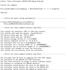
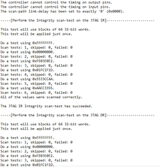
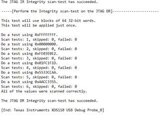
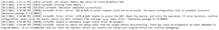
But after connecting XDS200 we are facing issue with the target connections. We are getting below error while target connection. 

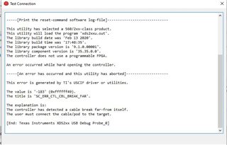
Please assist to resolve the above issue.

  • Hello Amit,

    The nTRST should be pulled down on your board. 

    If the trace of JTAG signals on your PCB board is long, please add series termination resistors on JTAG signal to reduce the signal reflection.

    http://software-dl.ti.com/hercules/hercules_docs/latest/hercules/Hardware_Kits/hardware_kits.html#debug-interface-jtag-signals

  • Hi QJ Wang,

    We followed the same instructions that you provided. We are getting same issue as shown in previous question with the XDS200. On the other hand, we tried to connect XDS110 on our board. Target configuration was made successfully. Please find the below screenshot for the same.


    But while running program in debug mode we are facing issue. Screenshot for the same has been added below.

    Please suggest some debugging instructions.

  • Hello,

    From your last screenshot, target is Jtag connected, and flash is erased successfully. When did you get the error message (-242, -1170)? 

  • Hi 

    We got this error message (-242, -1170) while programming MCU in debug mode after target configuration was successful using CCS on 7/10/2021. Also when we try to erase flash using uniflash it was done till bank 7 sector 31 after that same error was displayed. Complete erase of flash was not done using uniflash.

  • We got this error message (-242, -1170) while programming MCU in debug mode after target configuration was successful using CCS on 7/10/2021. Also when we try to erase flash using uniflash it was done till bank 7 sector 31 after that same error was displayed.

    Since the errors occur part way through the flash programming or erase perhaps a hardware issue with the custom board.

    Can you check the supply voltages for any dips which when the errors occur?

    E.g. on the flash VCCP pump supply.

  • Hi Chester

    • Today we removed MCU from one of the boards and checked the connections. All look fine.
    • Mounted fresh MCU on that board and tested.
    • Checked supply voltages and signal levels before flashing. All found OK.
    • JTAG connection test performed which is successful.
    • Next we started flashing MCU and we observed progress bar. At the end it gave following error


    *******************************************************

    CortexR5: GEL Output: Memory Map Setup for Flash @ Address 0x0CortexR5: GEL Output: Memory Map Setup for Flash @ Address 0x0 due to System Reset
    CortexR5: GEL Output: Memory Map Setup for Flash @ Address 0x0 due to System Reset
    CortexR5: Error: (Error -242 @ 0x0) A router subpath could not be accessed. The board configuration file is probably incorrect. (Emulation package 9.1.0.00001)
    CortexR5: Error: (Error -1170 @ 0x0) Unable to access the DAP. Reset the device, and retry the operation. If error persists, confirm configuration, power-cycle the board, and/or try more reliable JTAG settings (e.g. lower TCLK). (Emulation package 9.1.0.00001)
    CortexR5: Unable to determine target status after 20 attempts
    CortexR5: Failed to remove the debug state from the target before disconnecting. There may still be breakpoint op-codes embedded in program memory. It is recommended that you reset the emulator before you connect and reload your program before you continue debugging

    ******************************************************

    • Also, seen current increased on power supply. It was around 500mA from 5V input to board.
    • Stopped debugger, still current consumption found fluctuating from 160mA to 350mA continuously.
    • Checked voltages on board. 3.3V was correct but 1.2 volt found to be around 0.8V fluctuating and error LED was flickering.

     I know MCU takes more current while flashing the code to MCU memory.

    1.2V LDO has 1.2A current capacity while MCU max current 990mA. Bit close but looks OK.

    Please help us to understand what happens to MCU while programing which disturbs its core voltage permanently.

    Any preconditions has to be set in CCS or UNIFLASH to flash the MCU for the very first time. Note that same code and workspace has been used to flash on LAUNCHXL2-570LC43 and it is successful.

    Kindly suggest resolution urgently. Can we connect to check the issue via web?

  • Please help us to understand what happens to MCU while programing which disturbs its core voltage permanently.

    I'm not a hardware designer, so not sure why that is happening. Hopefully one of the TI employees will be able to help.

    Are you able to post the hardware schematic?

  • Please check your board layout to make sure that the TCLK signal trace doesn't across slots or splits power/group plane in the adjacent PCB plane.

    When a trace crosses a split in the adjacent plane, the return current path is interrupted, and the current must find another way to get across the split, which forces it to flow in a much bigger loop. From a practical standpoint, for high-speed signals, EMI is related to loop area. If you want to minimize EMI, you must minimize loop area.