This thread has been locked.

If you have a related question, please click the "Ask a related question" button in the top right corner. The newly created question will be automatically linked to this question.

TMS570LS3137: Flash ECC errors (ESM Group 1 Channel 6 event). What is the cause?How to track?

Part Number: TMS570LS3137
Other Parts Discussed in Thread: HALCOGEN

Hello, 

We are developing products with your company's TMS570LS3137. In a recent software version, the chip reported an ERROR of ESM Group 1 Channel 6 Event.
The lookup manual finds that this means flash ECC has found a single-bit correctable error.
Our application scenario does not allow this error, even if it is correctable.

So, my question has the following three points:

1. What is the cause of this error?
In addition to hardware failures, what software operations can cause Flash ECC errors?
The MPU module of TMS570 can prevent unexpected flash write operations. Since rewriting flash is blocked, why does ecc check fail?

2. How can we track this problem?

3. I don't understand the meaning of bits[2:0] of FCOR_ERR_ADD register in the Technical Reference Manual, and the description of FCOR_ERR_POSbits[7:0]. Can you explain it in detail, for example?

Looking forward to your reply, thank you!

  • Hello,

    1. The failing address is programmed to FCOR_ERR_ADD register. The FEDACSTATUS register flags indicate the type of error.

        The MPU setting doesn't affect the flash write through the F021 flash APIs.

    2. Please check the following registers: FEDACSTATUS, FCOR_ERR_ADD, and FCOR_ERR_POS.

    3. FCOR_ERR_ADD[2:0] is byte-offset. 

        ERR_POS: The bit address of the single-bit error.

        What is the value of BUS2 field of FCOR_ERR_POS register?

  • Hello,

    1."The MPU setting doesn't affect The flash write through The F021 Flash APIs." That's right.However, the program in question does not use these interfaces to manipulate Flash.So, I have a guess, is it possible that our program overflowed and read a flash address without ECC encoding, causing ECC detection failure?The source of this read may be a read of data or a read of instructions.What do you think?

    2.We observed the state of these registers when the error occurred, as follows:

    FCORERRCNT:0x0
    FCORERRADD:0x5b50
    FCORERRPOS:0x0
    FEDACSTATUS:0x2

    Does this mean that the address in error is 0x5b50?
    Ecc encoding means that the bit0 under this address should be 0, but the value of bit1 is actually read as 1, so the ECC error is reported, is it understood like this?

    3.I do not quite understand which "BUS2 field of FCOR_ERR_POS register" you mean. Would you please check whether it has been included in the answer to question 2?

  • Does this mean that the address in error is 0x5b50?

    Yes, the 0x5b50 is error address

    Ecc encoding means that the bit0 under this address should be 0, but the value of bit1 is actually read as 1, so the ECC error is reported, is it understood like this?

    FEDACSTATUS:0x2 -->  single-bit error is detected and corrected on bus 1 (for main flash). 

    I do not quite understand which "BUS2 field of FCOR_ERR_POS register" you mean. Would you please check whether it has been included in the answer to question 2?

    The flash wrapper has two buses, the bus1 and bus2.

    The bus1 is used by the CPU to access the flash's normal sectors (bank 0 and bank 1) for which the program and data are stored. The CPU will use the bus2 to access the OTP sectors, EEPROM emulation flash bank. 

    When CPU accesses program flash (bank 0 and bank 1)  via bus1, the CPU's built-in SECDED logic will perform the ECC checking. Note this ECC logic is inside the CPU, not inside the flash wrapper. 

    Did you perform any flash selftest by injecting an ECC error?

  • Thank you
    1. We didn't use OTP sectors or EEPROM emulation flash bank.
    2. I did not deliberately inject this fault to verify it, it is our official application that reported this problem now, I want to find the exception code and fix it.
    The current 0x5b50 is just the wrong address. Is there any way we can find out which code is causing the problem?

  • 1. Load your *.out file to flash

    2. run your code and a predefined breakpoint somewhere at the beginning in _c_int00()

    3. open then dis-assembly window, then find the instruction at 0x5B50

  • To be honest, I know all the steps you're talking about.I don't get it. Is that how you get to the cause of the mistake?

    Do you think the error was caused by executing the instruction at 0x5B50?

  • What is the value of FEDACCTRL1 register?

  • hello QJ Wang,

    FRDCNTL:0x311
    FEDACCTRL1:0xa060a
    FEDACCTRL2:0x0

  • Thanks

    Yes, 0x5B50 is the error address. When either EOFEN or EZFEN enable bit is set (FEDACCTRL1[7:4]=0x6 in your setting), the error address is captured during errors .

  • thanks!
    Then what caused this mistake?
    Hardware failure? or Code overflow?

  • Hi shunyun,

    1. It might be a permanent fault in the flash memory. After flash erase operation, if the content of the location (0x5B50) and its corresponding ECC location is 0xFFFFFFFF, the flash should be fine. 

    2. It might be a transient fault. Can you check the ECC value for flash address 0x5B50? It should be located at 0xF0400000 + 0x5B50/8 = 0xF0400B6A.

    In c_int00() function, after the flash ECC is enable, does reading 0x5B50 cause any ECC error? What is at 0x5B50? Is it part of your code?

  • hi QJ,Long time no see.

    1.

    I modified the sys_link.cmd file and now the error address has changed to 0x1990.

    sys_link.cmd is configured as follows:

    MEMORY
    {

    VECTORS (X) : origin=0x00000000 length=0x00000020
    FLASH0 (RX) : origin=0x00000020 length=0x0017FFE0
    FLASH1 (RX) : origin=0x00180000 length=0x00180000
    STACKS (RW) : origin=0x08000000 length=0x0000C000
    RAM (RW) : origin=0x0800C000 length=0x00033F00
    USERDEFINE (RW) : origin=0x0803FF00 length=0x00000100

    }

    SECTIONS
    {

    .intvecs : {} > VECTORS LOAD_START(__vectors_start)
    .text : {} > FLASH1
    .const : {} > FLASH1
    .cinit : {} > FLASH1
    .pinit : {} > FLASH1
    .bss : {} > RAM
    .data : {} > RAM
    .sysmem : {} > RAM

    }

    As you can see, 0x1990 is not used in my program because each immutable segment is stored with FLASH1.

    As you suggested, I checked the values under the following address:

    The value under address 0x1990 is  0xFFFF FFFF

    0xF0400000 + 0x1990/8 = 0xF040  0332 ,   The value under address 0xF040  0330 is 0x0997 0997

    2.

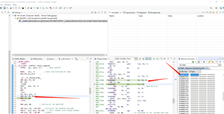
    In debug mode, I put the breakpoint in the ESM interrupt service function. After stepping out of the interrupt function, the CPU jumps to the __aeabi_uidivmod function in u_div32.asm, which is the location of the red arrow in my attached image.If I keep going down, you can see that my C code does have a line of division.

    So, my question is, why is there an access error in the __aeabi_uidivmod function, and is this function flawed?After analyzing the assembly code of this function, there is basically no calculation between registers, there is no reading and writing memory, why can such errors occur?

    u_div32

  • Attached is the division statement I mentioned in writing in C:

    void intToAscii(UINT32 value,INT8 buffer[],UINT16 buffer_len)
    {
        UINT8 i = 0;
        UINT8 j = 0;
        UINT8 digit_start = 0;
        UINT16 digit = 0;
        UINT32 denom = 1000000000;
        UINT8  t_buffer[30] = {0};
    
        if (0 == value)
        {
            t_buffer[0] = '0';
            t_buffer[1] = '\0';
            j = 2;
        }
        else
        {
            for(i = 10; i > 0; i--)
            {
                digit = value / denom;
                if((1 == digit_start) || (digit != 0))
                {
                    digit_start = 1;
                    value %= denom;
                    t_buffer[j++] = (digit + '0');
                }
                else
                {
                    ;
                }
                denom /= 10;
            }
            buffer[j] = 0;/*ZSQ modify warning NULL -> 0 2021.4.25*/
        }
    
        if(j > buffer_len)
        {
    
        }
        else
        {
            CM_Memcpy(buffer,buffer_len,t_buffer,j);
        }
    
    
    }

  •  Perhaps it is due to the speculative fetch. 

    The Cortex-R4 CPU may generate speculative fetches to any location within the flash memory space. A speculative fetch to a location with invalid ECC, which is subsequently not used, will not create an abort, but will set the ESM flags for a correctable or uncorrectable error. An uncorrectable error will unconditionally cause the nERROR pin to toggle low. Therefore care must be taken to generate the correct ECC for the entire flash space (flash0 and flash1) including the holes between sections and any unused or blank Flash areas.

    Can you try ot generate ECC using Linker CMD file?

    http://software-dl.ti.com/hercules/hercules_docs/latest/hercules/How_to_Guides/index.html

  • I have tried disabling Flashecc, and this error does not occur again, and the program runs stably.

    So I am almost sure that the full range of ECC coding, as you mentioned, will definitely prevent this problem from recurring.But just because a problem doesn't recur doesn't mean it's solved.You're also saying that maybe, how do I know that it's the speculative fetch that leads to it?

  • The recommendation to fill the holes with their respective ECC values is to avoid un-correctable ECC error due to speculative fetch. Please refer to TMS570LS3137 TRM: 5.3.1 SECDED Initialization

    ARM Cortex-R TRM: 5.1 About the prefetch unit (PFU):

    The purpose of the PFU is to:
    • perform speculative fetch of instructions ahead of the DPU by predicting the outcome of branch instructions
    • format instruction data in a way that aids the DPU in efficient implementation.


    The PFU fetches instructions from the memory system under the control of the DPU, and the internal coprocessors CP14 and CP15. In ARM state the memory system can supply up to two instructions per cycle. The PFU buffers up to three instruction data fetches in its FIFO. There is an additional FIFO between the PFU and the DPU that can normally buffer up to eight instructions. This reduces or eliminates stall cycles after a branch instruction. This increases the performance of the processor.

  • I have ECC code for the whole flash, the problem does not repeat.

    I think that's the answer. Thank you for your many replies.

    More on that, I suggest you add this part of ecc configuration to link. CMD in your demo or HALCOGEN generated code, after all, this problem is not easy to locate.