This thread has been locked.

If you have a related question, please click the "Ask a related question" button in the top right corner. The newly created question will be automatically linked to this question.

EK-TM4C123GXL: SPI transfer from Arduino [Master] to EK-TM4C123GXL

Part Number: EK-TM4C123GXL
Other Parts Discussed in Thread: EK-TM4C1294XL

Hi all,

I'm trying to set up SPI communication between an Arduino Mega 2560 and a TI microcontroller. I am trying to set up the Arduino Mega 2560 as master and the TI controller as the slave. I want the master to continously send 2 bytes in a single SPI transmission over and over again from the Arduino to the TI microcontroller.

Between the two boards, I have the following connections:

Arduino Mega 2560         EK-TM4C123GXL

PIN 50                      =>     PA5

PIN 51                      =>     PA4

PIN 52                      =>     PA2

PIN 53                      =>     PA3

It appears that the interrupt for SPI is called one time, and then does not get called again. It correctly transfers the first byte sent, but this first byte appears in both the 0 and 1 index of the storage array.

It does not appear that the interrupt gets called more than once. What's preventing the Arduino from correctly repeatedly transferring two bytes to the EK-TM4C123GXL?

Code for Arduino:

#include<SPI.h>

byte direction_byte = 0b00001110; 
byte speed_byte =     0b01010101;
//SPISettings ti_settings(SPI_CLOCK_DIV4,MSBFIRST,SPI_MODE2);

bool flip = 0;
void setup (void)
{

  digitalWrite(SS, HIGH);  // ensure SS stays high for now
  SPI.setDataMode(SPI_MODE2);
  // Put SCK, MOSI, SS pins into output mode
  // also put SCK, MOSI into LOW state, and SS into HIGH state.
  // Then put SPI hardware into Master mode and turn SPI on
  SPI.begin ();

  // Slow down the master a bit
  SPI.setClockDivider(SPI_CLOCK_DIV8);
  SPI.setDataMode(SPI_MODE2);
}  // end of setup


void loop (void)
{

  // enable Slave Select
  digitalWrite(SS, LOW);    // SS is pin 10

  // send test string


    SPI.transfer(direction_byte);


    SPI.transfer(speed_byte);

  
  // disable Slave Select
  digitalWrite(SS, HIGH);

  delay (1000);  // 1 seconds delay
}  // end of loop

Code for EK-TM4C123GXL:

//*****************************************************************************
//
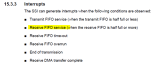
// spi_slave.c - Example demonstrating how to configure RX timeout interrupt in
// SPI slave mode.
//
// Copyright (c) 2013 Texas Instruments Incorporated.  All rights reserved.
// TI Information - Selective Disclosure
//
//*****************************************************************************

#include <stdbool.h>
#include <stdint.h>
#include "inc/hw_ints.h"
#include "inc/hw_memmap.h"
#include "driverlib/debug.h"
#include "driverlib/gpio.h"
#include "driverlib/interrupt.h"
#include "driverlib/pin_map.h"
#include "driverlib/pwm.h"
#include "driverlib/rom.h"
#include "driverlib/rom_map.h"
#include "inc/hw_memmap.h"
#include "driverlib/qei.h"
#include "driverlib/sysctl.h"
#include "driverlib/uart.h"
#include "utils/uartstdio.h"
#include "driverlib/fpu.h"
#include "inc/hw_types.h"
#include "inc/hw_memmap.h"
// The error routine that is called if the driver library encounters an error.
#include "inc/hw_types.h"                   // Defines common types and macros
#include "inc/hw_gpio.h"                    // Defines Macros for GPIO hardware
#include "inc/hw_qei.h"
#include "driverlib/ssi.h"

#include "utils/uartstdio.h"

//*****************************************************************************
//
//! \addtogroup ssi_examples_list
//! <h1>SPI Slave (spi_slave)</h1>
//!
//! This example configures the SSI0 as SPI Master, SSI2 as SPI Slave on an
//! EK-LM4F232 evaluation board.  RX timeout interrupt is configured for SSI2.
//! Three characters are sent on the master TX, then SSI2 RX timeout interrupt
//! is enabled. The code then waits for the interrupt to fire.  Once the
//! interrupt is fired the data from slave RX FIFO is read and compared to the
//! transmitted packet and the appropriate status is displayed.  If everything
//! goes well you should see a "Test Passed." message on the terminal window.
//! The status messages are transmitted over UART0 at 115200 baud and 8-n-1
//! mode.
//!
//! This example uses the following peripherals and I/O signals on EK-LM4F232.
//! You must review these and change as needed for your own board:
//! - SSI0 peripheral
//! - GPIO Port A peripheral (for SSI0 pins) (available near the SD card slot)
//! - SSI0CLK - PA2
//! - SSI0Fss - PA3
//! - SSI0Rx  - PA4
//! - SSI0Tx  - PA5
//!
//! - SSI2 peripheral
//! - GPIO Port M peripheral (for SSI2 pins) (available right below the OLED)
//! - SSI2CLK - PH4
//! - SSI2Fss - PH5
//! - SSI2Rx  - PH6
//! - SSI2Tx  - PH7
//!
//! For this example to work, the following connections are needed on the
//! EK-LM4F232 evaluation board.
//! - SSI0CLK(PA2) - SSI2CLK(PH4)
//! - SSI0Fss(PA3) - SSI0Fss(PH5)
//! - SSI0Rx(PA4)  - SSI2Tx(PH7)
//! - SSI0Tx(PA5)  - SSI2Rx(PH6)
//!
//! The following UART signals are configured only for displaying console
//! messages for this example.  These are not required for operation of SSI0.
//! - UART0 peripheral
//! - GPIO Port A peripheral (for UART0 pins)
//! - UART0RX - PA0
//! - UART0TX - PA1
//!
//! This example uses the following interrupt handlers.  To use this example
//! in your own application you must add these interrupt handlers to your
//! vector table.
//! - SSI2IntHandler.
//!
//
//*****************************************************************************

//*****************************************************************************
//
// Number of bytes to send and receive.
//
//*****************************************************************************
#define NUM_SSI_DATA 2

//*****************************************************************************
//
// Global variables used in interrupt handler and the main loop.
//
//*****************************************************************************
//volatile unsigned long g_ulSSI2RXTO = 0;
//unsigned long g_ulDataRx2[NUM_SSI_DATA];

volatile uint32_t g_ulSSI2RXTO = 0;
volatile uint32_t g_ulDataRx2[NUM_SSI_DATA];
//*****************************************************************************
//
// Interrupt handler for SSI2 peripheral in slave mode.  It reads the interrupt
// status and if the interrupt is fired by a RX time out interrupt it reads the
// SSI2 RX FIFO and increments a counter to tell the main loop that RX timeout
// interrupt was fired.
//
//*****************************************************************************
void
SSI0IntHandler(void)
{
    unsigned long ulStatus, ulIndex;

    //
    // Read interrupt status.
    //
    ulStatus = SSIIntStatus(SSI0_BASE, 1);

    //
    // Check the reason for the interrupt.
    //
    if(ulStatus & SSI_RXTO)
    {
        //
        // Interrupt is because of RX time out.  So increment counter to tell
        // main loop that RX timeout interrupt occurred.
        //
        g_ulSSI2RXTO++;

        //
        // Read NUM_SSI_DATA bytes of data from SSI2 RX FIFO.
        //
        for(ulIndex = 0; ulIndex < NUM_SSI_DATA; ulIndex++)
        {
            SSIDataGet(SSI0_BASE, &g_ulDataRx2[ulIndex]);
        }

        g_ulSSI2RXTO--;
    }

    //
    // Clear interrupts.
    //
    SSIIntClear(SSI2_BASE, ulStatus);
}

//*****************************************************************************
//
// This function sets up UART0 to be used for a console to display information
// as the example is running.
//
//*****************************************************************************

//*****************************************************************************
//
// This function sets up SPI0 to be used as Master in freescale mode.
//
//*****************************************************************************
void
InitSPI0(void)
{
    //
    // The SSI0 peripheral must be enabled for use.
    //
    SysCtlPeripheralEnable(SYSCTL_PERIPH_SSI0);

    while (!SysCtlPeripheralReady(SYSCTL_PERIPH_SSI0))
    {
    }
    //
    // For this example SSI2 is used with PortH[7:4].  GPIO port H needs to be
    // enabled so these pins can be used.
    //
    SysCtlPeripheralEnable(SYSCTL_PERIPH_GPIOA);

    while (!SysCtlPeripheralReady(SYSCTL_PERIPH_GPIOA))
    {
    }
    //
    // Configure the pin muxing for SSI2 functions on port H4, H5, H6 and H7.
    // This step is not necessary if your part does not support pin muxing.
    //
    GPIOPinConfigure(GPIO_PA2_SSI0CLK);
    GPIOPinConfigure(GPIO_PA3_SSI0FSS);
    GPIOPinConfigure(GPIO_PA4_SSI0RX);
    GPIOPinConfigure(GPIO_PA5_SSI0TX);

    GPIOPinTypeSSI(GPIO_PORTA_BASE, GPIO_PIN_5 | GPIO_PIN_4 | GPIO_PIN_3 | GPIO_PIN_2);

    SSIDisable(SSI0_BASE);
    //
    // Configure and enable the SSI0 port for SPI master mode.
    //
    SSIConfigSetExpClk(SSI0_BASE, SysCtlClockGet(), SSI_FRF_MOTO_MODE_2,
                       SSI_MODE_SLAVE, 660000, 8);

    SSIDisable(SSI0_BASE);

    //
    // Enable the SSI2 module.
    //
    SSIEnable(SSI0_BASE);

    IntEnable(INT_SSI0);

    SSIIntEnable(SSI0_BASE, SSI_RXTO);

    SSIIntRegister(SSI0_BASE, SSI0IntHandler);
}
//*****************************************************************************
//
// This function sets up SPI2 to be used as slave in freescale mode.
//
//*****************************************************************************
//*************************************************************************
int
main(void)
{
    /*
    unsigned long ulDataTx0[NUM_SSI_DATA];
    unsigned long ulDataRx0[NUM_SSI_DATA];
    unsigned long ulindex;
    */
    uint32_t ulDataTx0[NUM_SSI_DATA];
    uint32_t ulDataRx0[NUM_SSI_DATA];
    uint32_t ulindex;

    //
    // Set the clocking to run directly from the external crystal/oscillator.
    //
    SysCtlClockSet(SYSCTL_SYSDIV_1 | SYSCTL_USE_OSC | SYSCTL_OSC_MAIN | SYSCTL_XTAL_16MHZ);


    //
    // Init SPI0 as master.
    //
    InitSPI0();

    //
    // Read any residual data from the SSI port.  This makes sure the receive
    // FIFOs are empty, so we don't read any unwanted junk.  This is done here
    // because the SPI SSI mode is full-duplex, which allows you to send and
    // receive at the same time.  The SSIDataGetNonBlocking function returns
    // "true" when data was returned, and "false" when no data was returned.
    // The "non-blocking" function checks if there is any data in the receive
    // FIFO and does not "hang" if there isn't.  This might not be needed here.
    //
    while(SSIDataGetNonBlocking(SSI0_BASE, &ulDataRx0[0]))
    {
    }


    //
    // Clear any pending interrupt
    //
    SSIIntClear(SSI0_BASE, SSI_RXTO);


    while(1)
    {
    }
}

  • It appears that the interrupt for SPI is called one time, and then does not get called again

    Who are you referring to that only interrupt one time? The Arduino or TM4C123? If you are referring to Arduino then I cannot help and support. That is not a TI product. If you are referring to TM4C123 then you only enable interrupt for timeout as you wrote SSIIntEnable(SSI0_BASE, SSI_RXTO). You didn't enable receive FIFO interrupt. You want to generate interrupt when data is received, not when timeout has expired. What if the master sends data to the slave steadily that never trips the timeout? In this case, no interrupt is generated, isn't? See below interrupt sources. Note that interrupt is only generated when the receive FIFO is at least half full. There are 8 entries in the RXFIFO. Therefore, at least 4 or more data in the RXFIFO will interrupt be generated. 

  • I believe I have corrected this issue, but I'm still facing the same issue. I'm still receiving the first byte in all four positions of my storage array, rather than the first byte appearing in the first position, the second byte appearing in the second position, etc.

    EK-TM4C123GXL Code:

    //*****************************************************************************
    //
    // project0.c - Example to demonstrate minimal TivaWare setup
    //
    // Copyright (c) 2012-2020 Texas Instruments Incorporated.  All rights reserved.
    // Software License Agreement
    //
    // Texas Instruments (TI) is supplying this software for use solely and
    // exclusively on TI's microcontroller products. The software is owned by
    // TI and/or its suppliers, and is protected under applicable copyright
    // laws. You may not combine this software with "viral" open-source
    // software in order to form a larger program.fs
    //
    // THIS SOFTWARE IS PROVIDED "AS IS" AND WITH ALL FAULTS.
    // NO WARRANTIES, WHETHER EXPRESS, IMPLIED OR STATUTORY, INCLUDING, BUT
    // NOT LIMITED TO, IMPLIED WARRANTIES OF MERCHANTABILITY AND FITNESS FOR
    // A PARTICULAR PURPOSE APPLY TO THIS SOFTWARE. TI SHALL NOT, UNDER ANY
    // CIRCUMSTANCES, BE LIABLE FOR SPECIAL, INCIDENTAL, OR CONSEQUENTIAL
    // DAMAGES, FOR ANY REASON WHATSOEVER.
    //
    // This is part of revision 2.2.0.295 of the EK-TM4C123GXL Firmware Package.
    //
    //*****************************************************************************
    #include <stdlib.h>
    #include <stdbool.h>
    #include <stdint.h>
    #include "inc/hw_ints.h"
    #include "inc/hw_memmap.h"
    #include "driverlib/debug.h"
    #include "driverlib/gpio.h"
    #include "driverlib/interrupt.h"
    #include "driverlib/pin_map.h"
    #include "driverlib/pwm.h"
    #include "driverlib/rom.h"
    #include "driverlib/rom_map.h"
    #include "driverlib/hw_memmap.h"
    #include "driverlib/qei.h"
    #include "driverlib/sysctl.h"
    #include "driverlib/uart.h"
    #include "utils/uartstdio.h"
    #include "driverlib/fpu.h"
    #include "inc/hw_types.h"
    #include "inc/hw_memmap.h"
    // The error routine that is called if the driver library encounters an error.
    #include "inc/hw_types.h"                   // Defines common types and macros
    #include "inc/hw_gpio.h"                    // Defines Macros for GPIO hardware
    #include "inc/hw_qei.h"
    #include "driverlib/timer.h"
    #include "driverlib/ssi.h"
    #include "motor.h"
    
    #ifdef DEBUG
    void
    __error__(char *pcFilename, uint32_t ui32Line)
    {
    }
    #endif
    
    // Definitions
    #define NUM_SSI_DATA 4


    volatile uint32_t g_ulSSI2RXTO = 0;
    uint32_t g_ulDataRx2[NUM_SSI_DATA];
    
    
    void
    SSI0IntHandler(void)
    {
        unsigned long ulStatus, ulIndex;
    
        //
        // Read interrupt status.
        //
        ulStatus = SSIIntStatus(SSI0_BASE, 1);
    
        //
        // Check the reason for the interrupt.
        //
        if(ulStatus & SSI_RXFF); //SSI_RXTO
        {
            //
            // Interrupt is because of RX time out.  So increment counter to tell
            // main loop that RX timeout interrupt occurred.
            //
            g_ulSSI2RXTO++;
    
            //
            // Read NUM_SSI_DATA bytes of data from SSI2 RX FIFO.
            //
            for(ulIndex = 0; ulIndex < NUM_SSI_DATA; ulIndex++)
            {
                SSIDataGet(SSI0_BASE, &g_ulDataRx2[ulIndex]);
            }
    
        }
    
        //
        // Clear interrupts.
        //
        SSIIntClear(SSI0_BASE, ulStatus);
    }
    
    //*****************************************************************************
    //
    // This function sets up SPI2 to be used as slave in freescale mode.
    //
    //*****************************************************************************
    void
    InitSPI0(void)
    {
        //
        // The SSI0 peripheral must be enabled for use.
        //
        SysCtlPeripheralEnable(SYSCTL_PERIPH_SSI0);
    
        while (!SysCtlPeripheralReady(SYSCTL_PERIPH_SSI0))
        {
        }
        //
        // For this example SSI0 is used with PortA[5:2].  GPIO port A needs to be
        // enabled so these pins can be used.
        //
        SysCtlPeripheralEnable(SYSCTL_PERIPH_GPIOA);
    
        while (!SysCtlPeripheralReady(SYSCTL_PERIPH_GPIOA))
        {
        }
        //
        // Configure the pin muxing for SSI0 functions on port A2, A3, A4, and A5.
        // This step is not necessary if your part does not support pin muxing.
        //
        GPIOPinConfigure(GPIO_PA2_SSI0CLK);
        GPIOPinConfigure(GPIO_PA3_SSI0FSS);
        GPIOPinConfigure(GPIO_PA4_SSI0RX);
        GPIOPinConfigure(GPIO_PA5_SSI0TX);
    
        //
        // Configure the GPIO settings for the SSI pins.  This function also gives
        // control of these pins to the SSI hardware.  Consult the data sheet to
        // see which functions are allocated per pin.
        // The pins are assigned as follows:
        //      PA5 - SSI0Tx
        //      PA4 - SSI0Rx
        //      PA3 - SSI0Fss
        //      PA2 - SSI0CLK
        //
        GPIOPinTypeSSI(GPIO_PORTA_BASE, GPIO_PIN_5 | GPIO_PIN_4 | GPIO_PIN_3 | GPIO_PIN_2);
    
        SSIDisable(SSI0_BASE);
            //
        //
        // Configure and enable the SSI2 port for SPI slave mode.
        //
        SSIConfigSetExpClk(SSI0_BASE, SysCtlClockGet(), SSI_FRF_MOTO_MODE_2,
                           SSI_MODE_SLAVE, 660000, 8);
    
        //
        // Enable the SSI2 module.
        //
        SSIEnable(SSI0_BASE);
    
        IntEnable(INT_SSI0);
    
        SSIIntEnable(SSI0_BASE, SSI_RXFF); //SSI_RXTO
    
        SSIIntRegister(SSI0_BASE, SSI0IntHandler);
    }
    //*****************************************************************************
    //
    // This example will send out 3 bytes of data from master, then waits for slave
    // RX timeout interrupt to fire (where these 3 bytes are read).  Then the sent
    // and returned data are compared to give out appropriate status messages on
    // UART0.
    //
    //*****************************************************************************
    
    int main(void)
    {
        //g_ulDataRx2[0] = 0b00001001;
        //g_ulDataRx2[1] = 0b11110110;
        ROM_FPULazyStackingEnable();
    
        //uint32_t ulDataRx0[NUM_SSI_DATA];
        uint32_t ulindex;


        //
        // Setup the system clock to run at 50 Mhz from PLL with crystal reference
        //
        SysCtlClockSet(SYSCTL_SYSDIV_1 | SYSCTL_USE_OSC |   SYSCTL_OSC_MAIN | SYSCTL_XTAL_16MHZ);
        //
        InitSPI0();
    
    
        while(SSIDataGetNonBlocking(SSI0_BASE, &g_ulDataRx2[0]))
        {
        }
    
        //
        // Clear any pending interrupt
        //
        SSIIntClear(SSI0_BASE, SSI_RXFF); //SSI_RXTO


        while(1)
        {
        }
    }


    Arduino Code:

    #include<SPI.h>
    
    byte send_byte1 = 0b00000001;
    byte send_byte2 = 0b00000010;
    byte send_byte3 = 0b00000011;
    byte send_byte4 = 0b00000100;
    byte receive;
    //SPISettings ti_settings(SPI_CLOCK_DIV4,MSBFIRST,SPI_MODE2);
    
    bool flip = 0;
    void setup (void)
    {
    
      digitalWrite(SS, HIGH);  // ensure SS stays high for now
      SPI.setDataMode(SPI_MODE2);
      // Put SCK, MOSI, SS pins into output mode
      // also put SCK, MOSI into LOW state, and SS into HIGH state.
      // Then put SPI hardware into Master mode and turn SPI on
      SPI.begin ();
    
      // Slow down the master a bit
      SPI.setClockDivider(SPI_CLOCK_DIV8);
      SPI.setDataMode(SPI_MODE2);
    }  // end of setup
    
    
    void loop (void)
    {
    
      // enable Slave Select
      digitalWrite(SS, LOW);    // SS is pin 10
    
      // send test string
    
    
        receive = SPI.transfer(send_byte1);
        receive = SPI.transfer(send_byte2);
        receive = SPI.transfer(send_byte3);
        receive = SPI.transfer(send_byte4);
        
      // disable Slave Select
      digitalWrite(SS, HIGH);
    
      delay (100);  // 1 seconds delay
    }  // end of loop

  • Do you have logic analyzer or scope to show what data is being put out by the master.

    What is the baud rate of the master?

     Is the master sending only four bytes or sending the four bytes repeatedly?

     It is US holiday and there will be delay in responses.

  • The master is sending four bytes repeatedly. The master is operating SPI at 4Ghz. I do not have access to a logic analyzer.

  • The master is operating SPI at 4Ghz

    Are you sure 4Ghz, not 4MHz? Here are some comments:

     - Maximum TM4C123 baudrate operating as a slave is 6.6Mhz (150ns period). See below. 

     - Both master and slave have the same baudrate. This means you cannot have your master operate at 4Mhz, let alone 4Ghz which is not possible. I will suggest you first try a simple common baudrate like 4Mhz or 1Mhz on both side. Once working, you can increase to higher baudrate but not exceeding 6.6Mhz as dictated in the datasheet. 

     - both master and slave must have the same polarity and phase. Mismatching polarity and phase between them definitely will not work.

      - Try transmitting only 4 bytes from the master. Once it is working, then increase to more bytes. After slave receives 4 bytes, it will generate an RXFF interrupt. You don't want to jam the bus when it is not working yet.

      - Check for any errors detected by the slave device. Are they any?

      - If you don't have a logic analyzer, then use a scope. If you have neither, I really don't know what to suggest. It is a fundamental tool to help debug. You can easily find out what is wrong on the bus. 


  • - I believe I have set the master and slave to the same baud rate, but I'm still getting the same result. I've tried setting both to 4Mhz, as shown in code below.

    - I have tried only transmitting four bytes, but had no luck with this also. I have altered the Arduino code to send four bytes every five seconds. Using debug in CCS, I can see that the interrupt is not firing every five seconds, but somewhere closer to twenty seconds.

    - Not sure how to check for errors on the slave device. More explanation would be appreciated.

    - I will have access to a scope tomorrow and will look at the waveforms then.

    I've run out of ideas for what could possibly be wrong. If you have any other suggestions after looking at my code, I would appreciate it.

    Arduino Code

    #include<SPI.h>
    
    byte send_byte1 = 0b00000001;
    byte send_byte2 = 0b00000010;
    byte send_byte3 = 0b00000011;
    byte send_byte4 = 0b00000100;
    byte receive;
    //SPISettings ti_settings(SPI_CLOCK_DIV4,MSBFIRST,SPI_MODE2);
    
    bool flip = 0;
    void setup (void)
    {
    
      digitalWrite(SS, HIGH);  // ensure SS stays high for now
      SPI.setDataMode(SPI_MODE2);
      // Put SCK, MOSI, SS pins into output mode
      // also put SCK, MOSI into LOW state, and SS into HIGH state.
      // Then put SPI hardware into Master mode and turn SPI on
      SPI.begin ();
    
      // Slow down the master a bit
      SPI.setClockDivider(SPI_CLOCK_DIV4);
      SPI.setDataMode(SPI_MODE2);
    }  // end of setup
    
    
    void loop (void)
    {
    
      // enable Slave Select
      digitalWrite(SS, LOW);    // SS is pin 10
    
      // send test string
    
    
        receive = SPI.transfer(send_byte1);
        receive = SPI.transfer(send_byte2);
        receive = SPI.transfer(send_byte3);
        receive = SPI.transfer(send_byte4);
        
      // disable Slave Select
      digitalWrite(SS, HIGH);
    
      delay (5000);  // 1 seconds delay
    
    
    }  // end of loop

    TI Controller Code

    //*****************************************************************************
    //
    // project0.c - Example to demonstrate minimal TivaWare setup
    //
    // Copyright (c) 2012-2020 Texas Instruments Incorporated.  All rights reserved.
    // Software License Agreement
    //
    // Texas Instruments (TI) is supplying this software for use solely and
    // exclusively on TI's microcontroller products. The software is owned by
    // TI and/or its suppliers, and is protected under applicable copyright
    // laws. You may not combine this software with "viral" open-source
    // software in order to form a larger program.fs
    //
    // THIS SOFTWARE IS PROVIDED "AS IS" AND WITH ALL FAULTS.
    // NO WARRANTIES, WHETHER EXPRESS, IMPLIED OR STATUTORY, INCLUDING, BUT
    // NOT LIMITED TO, IMPLIED WARRANTIES OF MERCHANTABILITY AND FITNESS FOR
    // A PARTICULAR PURPOSE APPLY TO THIS SOFTWARE. TI SHALL NOT, UNDER ANY
    // CIRCUMSTANCES, BE LIABLE FOR SPECIAL, INCIDENTAL, OR CONSEQUENTIAL
    // DAMAGES, FOR ANY REASON WHATSOEVER.
    //
    // This is part of revision 2.2.0.295 of the EK-TM4C123GXL Firmware Package.
    //
    //*****************************************************************************
    #include <stdlib.h>
    #include <stdbool.h>
    #include <stdint.h>
    #include "inc/hw_ints.h"
    #include "inc/hw_memmap.h"
    #include "driverlib/debug.h"
    #include "driverlib/gpio.h"
    #include "driverlib/interrupt.h"
    #include "driverlib/pin_map.h"
    #include "driverlib/pwm.h"
    #include "driverlib/rom.h"
    #include "driverlib/rom_map.h"
    #include "driverlib/hw_memmap.h"
    #include "driverlib/qei.h"
    #include "driverlib/sysctl.h"
    #include "driverlib/uart.h"
    #include "utils/uartstdio.h"
    #include "driverlib/fpu.h"
    #include "inc/hw_types.h"
    #include "inc/hw_memmap.h"
    // The error routine that is called if the driver library encounters an error.
    #include "inc/hw_types.h"                   // Defines common types and macros
    #include "inc/hw_gpio.h"                    // Defines Macros for GPIO hardware
    #include "inc/hw_qei.h"
    #include "driverlib/timer.h"
    #include "driverlib/ssi.h"
    #include "motor.h"
    
    #ifdef DEBUG
    void
    __error__(char *pcFilename, uint32_t ui32Line)
    {
    }
    #endif
    
    // Definitions
    #define NUM_SSI_DATA 4
    
    #define RIGHT_DIRECTION_MASK 0b00000011;
    #define LEFT_DIRECTION_MASK  0b00001100;
    
    #define RIGHT_SPEED_MASK 0b00001111;
    #define LEFT_SPEED_MASK  0b11110000;
    
    // Global Variables
    volatile uint32_t g_ulSSI2RXTO = 0;
    uint32_t g_ulDataRx2[NUM_SSI_DATA];
    
    volatile int count = 0;
    
    uint32_t g_ui32Flags;
    
    
    bool cw = true;
    bool ccw = false;
    
    uint8_t hi = 255;
    uint8_t lo = 0;
    
    uint32_t period = 5000; //20ms (16Mhz / 64pwm_divider / 50)
    uint32_t duty = 2500;    //1.5ms pulse width


    //volatile int qeiPosition;
    
    volatile float leftcurrentRPM;
    volatile float rightcurrentRPM;
    
    volatile float leftdesiredRPM = 0;
    volatile float rightdesiredRPM = 0;
    
    volatile float left_error = 0;
    volatile float right_error = 0;
    
    volatile float left_integrated_error_float = 0;
    volatile float right_integrated_error_float = 0;
    
    volatile float left_integrated_error = 0;
    volatile float right_integrated_error = 0;
    
    volatile float left_send_value_float = 1;
    volatile float right_send_value_float = 1;
    
    float left_kp = 0.1;
    float right_kp = 0.1;
    
    float left_ki = 0.02;
    float right_ki = 0.02;
    
    volatile int left_send_value_int = 0;
    volatile int right_send_value_int = 0;


    // Function Declarations
    
    void ConfigureTimers(void);
    void Timer0IntHandler(void);
    void Timer1IntHandler(void);
    void delayMS(int ms);
    
    void initMotorControl(uint32_t period, uint32_t duty);
    void ConfigureEncoder(void);
    void left_motor(bool direction, uint8_t percent);
    void right_motor(bool direction, uint8_t percent);
    
    void
    SSI0IntHandler(void)
    {
        unsigned long ulStatus, ulIndex;
    
        //
        // Read interrupt status.
        //
        ulStatus = SSIIntStatus(SSI0_BASE, 1);
    
        //
        // Check the reason for the interrupt.
        //
        if(ulStatus & SSI_RXFF); //SSI_RXTO
        {
            //
            // Interrupt is because of RX time out.  So increment counter to tell
            // main loop that RX timeout interrupt occurred.
            //
            g_ulSSI2RXTO++;
    
            //
            // Read NUM_SSI_DATA bytes of data from SSI2 RX FIFO.
            //
            for(ulIndex = 0; ulIndex < NUM_SSI_DATA; ulIndex++)
            {
                SSIDataGet(SSI0_BASE, &g_ulDataRx2[ulIndex]);
            }
    
        }
    
        //
        // Clear interrupts.
        //
        SSIIntClear(SSI0_BASE, ulStatus);
    }
    
    //*****************************************************************************
    //
    // This function sets up SPI2 to be used as slave in freescale mode.
    //
    //*****************************************************************************
    void
    InitSPI0(void)
    {
        //
        // The SSI0 peripheral must be enabled for use.
        //
        SysCtlPeripheralEnable(SYSCTL_PERIPH_SSI0);
    
        while (!SysCtlPeripheralReady(SYSCTL_PERIPH_SSI0))
        {
        }
        //
        // For this example SSI0 is used with PortA[5:2].  GPIO port A needs to be
        // enabled so these pins can be used.
        //
        SysCtlPeripheralEnable(SYSCTL_PERIPH_GPIOA);
    
        while (!SysCtlPeripheralReady(SYSCTL_PERIPH_GPIOA))
        {
        }
        //
        // Configure the pin muxing for SSI0 functions on port A2, A3, A4, and A5.
        // This step is not necessary if your part does not support pin muxing.
        //
        GPIOPinConfigure(GPIO_PA2_SSI0CLK);
        GPIOPinConfigure(GPIO_PA3_SSI0FSS);
        GPIOPinConfigure(GPIO_PA4_SSI0RX);
        GPIOPinConfigure(GPIO_PA5_SSI0TX);
    
        //
        // Configure the GPIO settings for the SSI pins.  This function also gives
        // control of these pins to the SSI hardware.  Consult the data sheet to
        // see which functions are allocated per pin.
        // The pins are assigned as follows:
        //      PA5 - SSI0Tx
        //      PA4 - SSI0Rx
        //      PA3 - SSI0Fss
        //      PA2 - SSI0CLK
        //
        GPIOPinTypeSSI(GPIO_PORTA_BASE, GPIO_PIN_5 | GPIO_PIN_4 | GPIO_PIN_3 | GPIO_PIN_2);
    
        SSIDisable(SSI0_BASE);
            //
        //
        // Configure and enable the SSI2 port for SPI slave mode.
        //
        SSIConfigSetExpClk(SSI0_BASE, SysCtlClockGet(), SSI_FRF_MOTO_MODE_2,
                           SSI_MODE_SLAVE, 400000, 8); // 660000
    
        //
        // Enable the SSI2 module.
        //
        SSIEnable(SSI0_BASE);
    
        IntEnable(INT_SSI0);
    
        SSIIntEnable(SSI0_BASE, SSI_RXFF); //SSI_RXTO
    
        SSIIntRegister(SSI0_BASE, SSI0IntHandler);
    }
    //*****************************************************************************
    //
    // This example will send out 3 bytes of data from master, then waits for slave
    // RX timeout interrupt to fire (where these 3 bytes are read).  Then the sent
    // and returned data are compared to give out appropriate status messages on
    // UART0.
    //
    //*****************************************************************************
    
    int main(void)
    {
        //g_ulDataRx2[0] = 0b00001001;
        //g_ulDataRx2[1] = 0b11110110;
        ROM_FPULazyStackingEnable();
    
        //uint32_t ulDataRx0[NUM_SSI_DATA];
        uint32_t ulindex;


        //
        // Setup the system clock to run at 16 Mhz from PLL with crystal reference
        //
        SysCtlClockSet(SYSCTL_SYSDIV_1 | SYSCTL_USE_OSC |   SYSCTL_OSC_MAIN | SYSCTL_XTAL_16MHZ);


        ConfigureTimers();
        ConfigureEncoder();
    
        initMotorControl(period, duty);
        enableHbridge();
        //
        // Init SPI2 as slave.
        //
        InitSPI0();
    
        //
        // Enable RX timeout interrupt.
        //
        //SSIIntEnable(SSI2_BASE, SSI_RXTO);
        //IntEnable(INT_SSI2);
        //
        // Read any residual data from the SSI port.  This makes sure the receive
        // FIFOs are empty, so we don't read any unwanted junk.  This is done here
        // because the SPI SSI mode is full-duplex, which allows you to send and
        // receive at the same time.  The SSIDataGetNonBlocking function returns
        // "true" when data was returned, and "false" when no data was returned.
        // The "non-blocking" function checks if there is any data in the receive
        // FIFO and does not "hang" if there isn't.
        //
        while(SSIDataGetNonBlocking(SSI0_BASE, &g_ulDataRx2[0]))
        {
        }
    
        //
        // Clear any pending interrupt
        //
        SSIIntClear(SSI0_BASE, SSI_RXFF); //SSI_RXTO
    
    // clock divider was 4
    
    
        UARTprintf("SSI ->\n");
        UARTprintf("  Mode: SPI\n");
        UARTprintf("  Data: 16-bit\n\n");


       QEIPositionSet(QEI0_BASE,170);
       QEIPositionSet(QEI1_BASE,170);
    
    
       //GPIOPinWrite(GPIO_PORTB_BASE, GPIO_PIN_0, 255);
    
       // left_motor(cw, 75);
       // right_motor(cw, 75);
    
        while(1)
        {
    
    
            // Right Motor Control:
            uint8_t right_dir_mask_result = g_ulDataRx2[0] & RIGHT_DIRECTION_MASK;
            uint8_t right_spd_mask_result = g_ulDataRx2[1] & RIGHT_SPEED_MASK;
    
            right_spd_mask_result = 14 * right_spd_mask_result;
    
            if( (right_dir_mask_result == 0) || (right_dir_mask_result == 3) )
            {
               // right_motor(ccw,0);
            }
            if(right_dir_mask_result == 1)
            {
               // right_motor(ccw,right_spd_mask_result);
            }
            if(right_dir_mask_result == 2)
            {
               // right_motor(cw,right_spd_mask_result);
            }
    
            // Left Motor Control
            uint8_t left_dir_mask_result = g_ulDataRx2[0] & LEFT_DIRECTION_MASK;
            uint8_t left_spd_mask_result = g_ulDataRx2[1] & LEFT_SPEED_MASK;
    
            if(left_spd_mask_result > 0)
            {
               // left_spd_mask_result = (left_spd_mask_result >> 4);
            }
    
            left_spd_mask_result = 14* left_spd_mask_result;
    
            if( (left_dir_mask_result == 0b00000000) || (left_dir_mask_result == 0b00001100) )
            {
               // left_motor(ccw,0);
            }
            if(left_dir_mask_result == 0b00000100)
            {
               // left_motor(ccw,left_spd_mask_result);
            }
            if(left_dir_mask_result == 0b00001000)
            {
              //  left_motor(cw,left_spd_mask_result);
            }
    
        }
    }


    void ConfigureTimers(void){
        //
        // Enable the GPIO port that is used for the on-board LED.
        //
        ROM_SysCtlPeripheralEnable(SYSCTL_PERIPH_GPIOF);
    
        //
        // Enable the GPIO pins for the LED (PF1 & PF2).
        //
        ROM_GPIOPinTypeGPIOOutput(GPIO_PORTF_BASE, GPIO_PIN_2 | GPIO_PIN_1);
    
    
        //
        // Enable the peripherals used by this example.
        //
        ROM_SysCtlPeripheralEnable(SYSCTL_PERIPH_TIMER0);
        ROM_SysCtlPeripheralEnable(SYSCTL_PERIPH_TIMER1);
    
        //
        // Enable processor interrupts.
        //
        ROM_IntMasterEnable();
    
        //
        // Configure the two 32-bit periodic timers.
        //
        ROM_TimerConfigure(TIMER0_BASE, TIMER_CFG_PERIODIC);
        ROM_TimerConfigure(TIMER1_BASE, TIMER_CFG_PERIODIC);
        ROM_TimerLoadSet(TIMER0_BASE, TIMER_A, ROM_SysCtlClockGet());
        ROM_TimerLoadSet(TIMER1_BASE, TIMER_A, ROM_SysCtlClockGet() / 10); // was ROM_SysCtlClockGet() / 2
    
        //
        // Setup the interrupts for the timer timeouts.
        //
        ROM_IntEnable(INT_TIMER0A);
        ROM_IntEnable(INT_TIMER1A);
        ROM_TimerIntEnable(TIMER0_BASE, TIMER_TIMA_TIMEOUT);
        ROM_TimerIntEnable(TIMER1_BASE, TIMER_TIMA_TIMEOUT);
    
        //
        // Enable the timers.
        //
        ROM_TimerEnable(TIMER0_BASE, TIMER_A);
        //ROM_TimerEnable(TIMER1_BASE, TIMER_A);
    
        //
        // Loop forever while the timers run.
        //
    
    }
    
    void Timer0IntHandler(void)
    {
    
        // LEFT MOTOR
        leftcurrentRPM = (QEIVelocityGet(QEI0_BASE) * 60)/(374*4);
            // Calculate error and proportional value.
            left_error = leftdesiredRPM - leftcurrentRPM;
            // Calculate error and integral value.
            left_integrated_error_float += left_error;
            // Return the PID controlled duty cycle value.
            left_send_value_float += ((left_kp*left_error + left_ki*left_integrated_error_float));
    
            left_send_value_int = (int) left_send_value_float;
    
            if(left_send_value_int < 99 && left_send_value_int > 0)
            {
                PWMPulseWidthSet(PWM0_BASE, PWM_OUT_1, ((period* left_send_value_int)/100) );
            }
            if(left_send_value_int <= 0){
                PWMPulseWidthSet(PWM0_BASE, PWM_OUT_1, ((period* 0)/100) );
            }
            if(left_send_value_int >= 99){
                        PWMPulseWidthSet(PWM0_BASE, PWM_OUT_1, ((period* 99)/100) );
                    }
    
    
         // RIGHT MOTOR
         rightcurrentRPM = (QEIVelocityGet(QEI1_BASE) * 60)/(374*4);
             // Calculate error and proportional value.
             right_error = rightdesiredRPM - rightcurrentRPM;
             right_integrated_error_float += right_error;
             // Return the PID controlled duty cycle value.
             right_send_value_float += ((right_kp*right_error + right_ki*right_integrated_error_float));
             right_send_value_int = (int) right_send_value_float;
             if(right_send_value_int < 99 && right_send_value_int > 0)
             {
                 //motor(ccw,send_value_int);
                 PWMPulseWidthSet(PWM0_BASE, PWM_OUT_0, ((period* right_send_value_int)/100) );
             }
             if(right_send_value_int <= 0){
                 PWMPulseWidthSet(PWM0_BASE, PWM_OUT_1, ((period* 0)/100) );
             }
             if(right_send_value_int >= 99){
                         PWMPulseWidthSet(PWM0_BASE, PWM_OUT_1, ((period* 99)/100) );
                     }


        count = count + 1;
        //


        // Clear the timer interrupt.
        //
        ROM_TimerIntClear(TIMER0_BASE, TIMER_TIMA_TIMEOUT);
    
        //
        // Toggle the flag for the first timer.
        //
        HWREGBITW(&g_ui32Flags, 0) ^= 1;
    
        //
        // Use the flags to Toggle the LED for this timer
        //
        GPIOPinWrite(GPIO_PORTF_BASE, GPIO_PIN_1, g_ui32Flags << 1);
    
        ROM_IntMasterDisable();
    
        ROM_IntMasterEnable();
    }
    
    
    void
    Timer1IntHandler(void)
    {
        //char cOne, cTwo;
    
        //
        // Clear the timer interrupt.
        //
        ROM_TimerIntClear(TIMER1_BASE, TIMER_TIMA_TIMEOUT);
    
        //
        // Toggle the flag for the second timer.
        //
        HWREGBITW(&g_ui32Flags, 1) ^= 1;
    
        //
        // Use the flags to Toggle the LED for this timer
        //
        GPIOPinWrite(GPIO_PORTF_BASE, GPIO_PIN_2, g_ui32Flags << 1);
        //count = count + 1;
    
        //
        ROM_IntMasterDisable();
    
        ROM_IntMasterEnable();
    
    }
    
    void delayMS(int ms) {
        SysCtlDelay( (SysCtlClockGet()/(3*1000))*ms ) ;
    }


  • I will wait for your scope waveform to comment further. Please also note there is a ssi example in C:\ti\TivaWare_C_Series-2.2.0.295\examples\boards\ek-tm4c1294xl\ssi_master_slave_xfer that you can reference. This example setups one SSI module as a master and another SSI as a slave. You will need to make connections between them on the board. Although this example is for TM4C129, you can modify or just read it for TM4C123.