Hello,
I am currently in the process of writing an abstraction for interrupts in our TI-RTOS based system using the MCU+-SDK for AM64x-Sitara.
My area of application for interrupts is currently GPIOs, but I would like to have a standard interface for interrupts.
My problem here is that I seem to be droning in different ID numbers, where I am not aware why I need all those.
I would be happy if you could correct me where I am wrong.
My current understanding
*******************************************************************************************
When I am on my home PC, I got a single processor with, I guess a single interrupt controller.
There are IRQ-Numbers, some are hardwired others can be set in the BIOS.
They tell the processor which peripheral is responsible for triggering an interrupt.
On the AM64x we have multiple MCUs with several cores. So we need to not only set the interrupt source peripheral but also the interrupt destination MCU/Core.
Some peripherals have a direct interrupt line to a destination MCU. Here we use simply a HwIP_Params struct to
set the interrupt number of the concerning interrupt controller for the peripheral that triggered the interrupt.
Where that interrupt number is hardwired and described in the TRM.(Interrupt ID, for CORE0 R5F in Table 9-80 for instance).
Then we set an ISR as callback in the HwIP_Params struct and well I guess the priority is something we can set as we wish
according to how our set of interrupts looks like.
Now there are certain peripherals like GPIOs that don't have each a hardwired interrupt line to the destination MCU/Core.
Those use an interrupt router for muxing the interrupt to the desired destination.
This works by utilizing the TISCI interface, where requests to the DMSC subsystem take the form described here:
software-dl.ti.com/.../rm_irq.html
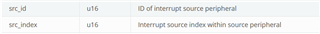
In my understanding all i need to provide to source index (src_index) connected to input index for the INTR, which is probably the device ID of the source peripheral (my GPIO for instance),
although the device ID of the source could also be the src_id. Here I don't understand the difference, maybe it is for SMDs with several pads, where the device ID is for the SMD
and the src_index is for the pad?
And then I need to provide the destination index (dst_host_irq) connected to output index for the INTR, which is probably the same as the IRQ number provided in the TRM in table 9-80?
Though in the description of "struct tisci_msg_rm_irq_set_req - Interrupt Router Mux Configuration" here
https://software-dl.ti.com/tisci/esd/latest/2_tisci_msgs/rm/rm_irq.html
it says that for a direct connection both src_id and dst_id are the device IDs of the interrupt router, which doesn't
make much sense to me. As I would think the dst_id should be that of the MCU and the src_id that of the peripheral.
Also when I look in the tables here:
http://software-dl.ti.com/tisci/esd/latest/5_soc_doc/am64x/interrupt_cfg.html
There seem to be some irregularities, at least in my understanding.
For instance, in table 9-80, TRM (R5FSS0_CORE0 Interrupt Map)
It says, interrupt number 43 (is intNum in HwIP_Params the same as interrupt-ID here?) is connected to INTR0 Output index 11.
which seems correct, when looking at the table here:
software-dl.ti.com/.../interrupt_cfg.html
but it says that the destination is GICSS, which is the interrupt controller for the Cortex-A53 and not the R5F like it says in the TRM.
So I am not sure if those numbers are just a coincidence here and if the HwIP_Params.intNum is really the Interrupt-ID and also the destination index of the INTR0.
If they are not the same, why do I need the intNum in addition to source and destination indexes. Shouldn't those 2 be enough to uniquely describe an interrupt line?
Next is the interrupt aggregator.
My understanding is, when I have a global event (like for instance "power down") which can be triggered by a multitude of sources, where it is not important which source triggered the event,
those events are mapped to virtual interrupts. Those VINTs are bitsets which are connected to a hardwired destination identified by a destination index.
The destination can be either an interrupt controller of one of the MCUs/Cores or an INTR.
A bit in the vint can be mapped to a global event, so that when the event occurs the destination is notified about the bit change.
The mapping of the global event to the vint is kept in those INTA registers described here:
https://git.kernel.org/pub/scm/linux/kernel/git/torvalds/linux.git/tree/Documentation/devicetree/bindings/interrupt-controller/ti,sci-inta.yaml
where I guess those are the same as the OES registers described here:
https://software-dl.ti.com/tisci/esd/latest/2_tisci_msgs/rm/rm_irq.html#tisci-msg-rm-irq-set-irq-route-set
I would assume the INTA/OES register is also the place where the vint_status_bit_index is kept.
*******************************************************************************************
So if my understanding is correct, the things that I need the user of an interrupt interface to provide are
1. a source index
2. a destination index
3. in case of a virtual interrupt a global event
The rest should be able to deduce internally.
Is that correct?
(Plase don't simply answer with yes/no, since I had more questions above)
Thank you for your time and trouble.
Best regards
Philip.