Other Parts Discussed in Thread: SN75468,
Hello,
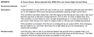
We are using GPIO points PF0 through PF4 from a TM4C1237H6PM to drive a Darlington transistor array (TI SN75468). During ESD testing, we have found that discharges seem to couple to the uP through the Darlington to the port pin and in some way alter the configuration or function of the pins. Prior to the discharge, they function properly. After the discharge, pins that were on are functionally off, or perhaps tri-stated. They tend to be locked off with a slight current leakage. Reasserting "on" does not help. Asserting "off" and then asserting "on" again returns the GPIO pin to normal function. Also, shorting the GPIO pin to ground returns it to normal function as well. There also seems to be an increase in our supply current to the uP when one of the GPIO pins is in this state.
Placing a resistor between the Darlington and the GPIO pin appears to fix the issue, as does placing a capacitance from each port pin to ground, but it appears to need to be >0.1uF. Our current assumption is that the ESD discharges seem to couple to ground and back through the protection diodes in the Darlington. Discharges to grounded leads or planes near to the device couple and cause the issue if it does not have one of these mitigations.
Some questions:
- Do you have experience with voltage disturbances on GPIO pins confusing the configuration or function of the GPIO pins, perhaps something along the line of a FET latch-up event? If so, do you know the root cause and how to mitigate against it?
- As mentioned, toggling the GPIO off and then on again seems to fix the issue. Do you have any idea as to why, and how long it might need to be off?
- I did not find a discussion in the manual (I may have missed it) of how the GPIO pins react to attempts to pull more current from them than they are configured for, i.e. a GPIO attached to a capacitor through a resistor that does not limit its maximum current to its configuration for 2, 4, or 8ma. Will there be a problem if the GPIO is set to 2 ma, but would nominally draw 10 ma for a ms or so?
- Can you share the output circuit of the GPIO so that we can review what might be happening?
Thanks,
Mike


