This thread has been locked.

If you have a related question, please click the "Ask a related question" button in the top right corner. The newly created question will be automatically linked to this question.

TMS570LC4357: TMS570LC4357

Part Number: TMS570LC4357

Hi, thank you for all the previous support.

I am currently working with TMS570 LC4357 Development Board as discussed before:

TMDX570LC43HDK Development kit | TI.com

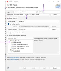
The setup looks like this:
I checked the Terminal Connection and it gives me the following error:

//

An error occurred while hard opening the controller.

-----[An error has occurred and this utility has aborted]--------------------

This error is generated by TI's USCIF driver or utilities.

The value is '-180' (0xffffff4c).
The title is 'SC_ERR_CTL_NO_TRG_POWER'.

The explanation is:
The controller has detected a target power loss.
The user must turn-on or connect the power supply for the target.

[End: Texas Instruments XDS100v2 USB Debug Probe_0]

//

  • Never Mind, Got it resolved. It was a power issue

    I still would like to understand how this code works:

    void main(void)
    {
    /* USER CODE BEGIN (3) */
    
        /* Initialize RTI driver */
        rtiInit();
    
        /* Set high end timer GIO port hetPort pin direction to all output */
        gioSetDirection(hetPORT1, 0xFFFFFFFF);
    
        /* Enable RTI Compare 0 interrupt notification */
        rtiEnableNotification(rtiREG1,rtiNOTIFICATION_COMPARE0);
    
        /* Enable IRQ - Clear I flag in CPS register */
        /* Note: This is usually done by the OS or in an svc dispatcher */
        _enable_IRQ_interrupt_();
    
        /* Start RTI Counter Block 0 */
        rtiStartCounter(rtiREG1,rtiCOUNTER_BLOCK0);
    
        /* Run forever */
        while(1);
    
    /* USER CODE END */
    }
    
    /* USER CODE BEGIN (4) */
    
    
    /* Note-You need to remove rtiNotification from notification.c to avoid redefinition */
    void rtiNotification(rtiBASE_t *rtiREG, uint32 notification)
    {
    /*  enter user code between the USER CODE BEGIN and USER CODE END. */
        /* Toggle HET pin 0 */
        gioSetPort(hetPORT1, gioGetPort(hetPORT1) ^ 0x00000001);
    }
    /* USER CODE END */

    I would like to know where are the port names mentioned for every GPIO Pins or LEDs.

    This above example code sets hetPORT1 to 0xFFFFFFFF I guess, which I assume is making it active

    What do "getSetDirection" and "getSetPort", do??

  • I also have the CCS Workspace, Project and HAL Project setup in one folder where I am able to run all the example codes of HAL. Now I want to deploy my own Code structured in Visual Studio format with SRC, INCLUDE and TOOLS folder format. I wanted to know the steps to add these into the CCS Project include and deploy these codes into the MCU

    Looking forward to your reply,

    Thanks,

    Warm Regards,

    Aadi

  • Hi Aadi,

    You can add your own files to CCS project. For more information adding/linking files, please see:
    processors.wiki.ti.com/.../Projects_and_Build_Handbook_for_CCS