This thread has been locked.

If you have a related question, please click the "Ask a related question" button in the top right corner. The newly created question will be automatically linked to this question.

TM4C123GH6PGE: Facing issue while programming

Part Number: TM4C123GH6PGE

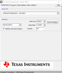
Hi, I am using C232HD-DDHSP-0 UART cable for USB to UART communication, I am also using LM flash Programmer, after that I am getting the error like this, could you pls clarify on this.

  • Hi,

      I can't see your image. Can you please upload? You can just drag your image into the editing window.

      Please provide some information.

      - Are you using a bootloader to download your firmware?

      - Are you using the ROM-based bootloader or the flash-based bootloader?

      - Which UARTx are you using? Please note that if you use ROM-based bootloader, it will only work with UART0. If you want to UART1 or UART2 or so forth, you must use the flash-based bootloader.

      - If you are using the flash-based bootloader, did you change the below #define in the bl_config.h according to the UART instance you want to use?

    //*****************************************************************************
    //
    // Selects the clock enable for the UART peripheral module
    //
    // Depends on: UART_ENABLE_UPDATE
    // Exclusive of: None
    // Requires: UARTx_BASE
    //
    //*****************************************************************************
    #define UART_CLOCK_ENABLE     SYSCTL_RCGCUART_R0
    
    //*****************************************************************************
    //
    // Selects the base address of the UART peripheral module
    //
    // Depends on: UART_ENABLE_UPDATE
    // Exclusive of: None
    // Requires: UART_CLOCK_ENABLE
    //
    //*****************************************************************************
    #define UARTx_BASE     UART0_BASE
    
    //*****************************************************************************
    //
    // Selects the clock enable for the GPIO corresponding to UART RX pin
    //
    // Depends on: UART_ENABLE_UPDATE
    // Exclusive of: None
    // Requires: UART_RXPIN_BASE, UART_RXPIN_PCTL and UART_RXPIN_POS
    //
    //*****************************************************************************
    #define UART_RXPIN_CLOCK_ENABLE     SYSCTL_RCGCGPIO_R0
    
    //*****************************************************************************
    //
    // Selects the base address for the GPIO corresponding to UART RX pin
    //
    // Depends on: UART_ENABLE_UPDATE
    // Exclusive of: None
    // Requires: UART_RXPIN_CLOCK_ENABLE, UART_RXPIN_PCTL and UART_RXPIN_POS
    //
    //*****************************************************************************
    #define UART_RXPIN_BASE     GPIO_PORTA_BASE
    
    //*****************************************************************************
    //
    // Selects the port control value for the GPIO corresponding to UART RX pin
    //
    // Depends on: UART_ENABLE_UPDATE
    // Exclusive of: None
    // Requires: UART_RXPIN_CLOCK_ENABLE, UART_RXPIN_BASE and UART_RXPIN_POS
    //
    //*****************************************************************************
    #define UART_RXPIN_PCTL     0x1
    
    //*****************************************************************************
    //
    // Selects the pin number for the GPIO corresponding to UART RX pin
    //
    // Depends on: UART_ENABLE_UPDATE
    // Exclusive of: None
    // Requires: UART_RXPIN_CLOCK_ENABLE, UART_RXPIN_BASE and UART_RXPIN_PCTL
    //
    //*****************************************************************************
    #define UART_RXPIN_POS     0
    
    //*****************************************************************************
    //
    // Selects the clock enable for the GPIO corresponding to UART TX pin
    //
    // Depends on: UART_ENABLE_UPDATE
    // Exclusive of: None
    // Requires: UART_TXPIN_BASE, UART_TXPIN_PCTL and UART_TXPIN_POS
    //
    //*****************************************************************************
    #define UART_TXPIN_CLOCK_ENABLE     SYSCTL_RCGCGPIO_R0
    
    //*****************************************************************************
    //
    // Selects the base address for the GPIO corresponding to UART TX pin
    //
    // Depends on: UART_ENABLE_UPDATE
    // Exclusive of: None
    // Requires: UART_TXPIN_CLOCK_ENABLE, UART_TXPIN_PCTL and UART_TXPIN_POS
    //
    //*****************************************************************************
    #define UART_TXPIN_BASE     GPIO_PORTA_BASE
    
    //*****************************************************************************
    //
    // Selects the port control value for the GPIO corresponding to UART TX pin
    //
    // Depends on: UART_ENABLE_UPDATE
    // Exclusive of: None
    // Requires: UART_TXPIN_CLOCK_ENABLE, UART_TXPIN_BASE and UART_TXPIN_POS
    //
    //*****************************************************************************
    #define UART_TXPIN_PCTL     0x1
    
    //*****************************************************************************
    //
    // Selects the pin number for the GPIO corresponding to UART TX pin
    //
    // Depends on: UART_ENABLE_UPDATE
    // Exclusive of: None
    // Requires: UART_TXPIN_CLOCK_ENABLE, UART_TXPIN_BASE and UART_TXPIN_PCTL
    //
    //*****************************************************************************
    #define UART_TXPIN_POS     1

       - To make sure there is nothing wrong with your USB to UART adapter, can you use the boot_serial (the bootloader) and boot_demo1 (the demo application) on UART0 for your custom board? The boot_serial and boot_demo1 should work out of the box on UART0 without any modification. 

      - What is your UART setting? Below is mine. My COM port will be different from yours. 

  • Hi,

      I have not heard back from you. I suppose you have resolved the issue. I will close this thread for now. If you have some update you can just write back to this post and the post will automatically reopen.