Am263 supports thermal management of the device by providing control of on-chip temperature sensors.
How to access these sensors to get the SOC temperature?
This thread has been locked.
If you have a related question, please click the "Ask a related question" button in the top right corner. The newly created question will be automatically linked to this question.
Am263 supports thermal management of the device by providing control of on-chip temperature sensors.
How to access these sensors to get the SOC temperature?
The device has two temperature sensors, each of which are located near hotspots in the device die. There are two additional temperature sensors located at other location in the device die.
The (CSL_TOP_CTRL_TSENSE_CFG) register needs to be configured to enable the temperature sensors.
//In order to enable temperature controller, below bits needs to be reset TMPSOFF, BGROFF, AIPOFF and SNSR_MX_HIZ bit
//The thermal FSM does read out of sensors in round robin fashion. The device has two temperature sensors, each of which are located near hotspots in the device die. There are two additional temperature sensors located at other location in the device die.
//SENSOR_SEL controls the enabling/disabling of individual sensors - 0x00000010U (CSL_TOP_CTRL_TSENSE_CFG_SENSOR_SEL_MASK)
//For each selected sensor, FSM requires anywhere between 51 to 54 clock cycles to start the sequence - 0x00003600(CSL_TOP_CTRL_TSENSE_CFG_DELAY_MASK)
//The start of temperature measurement is initiated automatically after the TOP_CTRL.TSENSE_CFG.ENABLE is set.
//The following piece of code configures the register:
/* Unlock Top Control Space */ SOC_controlModuleUnlockMMR(SOC_DOMAIN_ID_MAIN, TOP_CTRL_PARTITION0);
CSL_REG32_WR((CSL_TOP_CTRL_U_BASE + CSL_TOP_CTRL_TSENSE_CFG), ((CSL_REG32_RD(CSL_TOP_CTRL_U_BASE + CSL_TOP_CTRL_TSENSE_CFG)) & 0x0FFFF));
CSL_REG32_WR((CSL_TOP_CTRL_U_BASE + CSL_TOP_CTRL_TSENSE_CFG), ((CSL_REG32_RD(CSL_TOP_CTRL_U_BASE + CSL_TOP_CTRL_TSENSE_CFG))| (0x00000010U | 0x00003600)));
CSL_REG32_WR((CSL_TOP_CTRL_U_BASE + CSL_TOP_CTRL_TSENSE_CFG), ((CSL_REG32_RD(CSL_TOP_CTRL_U_BASE + CSL_TOP_CTRL_TSENSE_CFG))| 0x00000001U));
/* Lock Top Control Space */
SOC_controlModuleLockMMR(SOC_DOMAIN_ID_MAIN, TOP_CTRL_PARTITION0);
//To read the ADC value of corresponding temperature Value - .When the conversion is ongoing for a particular sensor, the corresponding //TOP_CTRL.TSENSE*_RESULT.EOCZ status bits are set to 0x1. The EOCZ bit is reset to 0 again when the conversion completes.
SOC_controlModuleUnlockMMR(SOC_DOMAIN_ID_MAIN, TOP_CTRL_PARTITION0);
while(((CSL_REG32_RD(CSL_TOP_CTRL_U_BASE + CSL_TOP_CTRL_TSENSE0_RESULT))& CSL_TOP_CTRL_TSENSE0_RESULT_ECOZ_MASK ) != 0);
DebugP_log("ADC Value from Sensor 1: %d\r\n", (CSL_REG32_RD(CSL_TOP_CTRL_U_BASE + CSL_TOP_CTRL_TSENSE0_RESULT)));
SOC_controlModuleLockMMR(SOC_DOMAIN_ID_MAIN, TOP_CTRL_PARTITION0);
The Output is obtained as shown below:

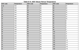
These ADC values can be interpreted as corresponding temperature values from the TRM at Table 6-13. ADC Values Versus Temperature

Other features of these temperature sensors are available in TRM at section: 6.2.2.3 Thermal Manager
Regards
Sri Vidya