This thread has been locked.

If you have a related question, please click the "Ask a related question" button in the top right corner. The newly created question will be automatically linked to this question.

TMS570LC4357: MIBSPI interface for TMS570 devices

Part Number: TMS570LC4357
Other Parts Discussed in Thread: HALCOGEN, RM57L843

Hello TI Team,

We've been working on MIBSPI interface development using TMS570LC4357 device. Even though many things have been understood and developed (using https://www.ti.com/tool/TMDX570LC43HDK), we are facing some challenges. 

Query:

We want to use MIBSPI1 of the device transfer 256 bytes of data. We also enabled extended buffer mode using MibSPIEN register. While debugging, we are able to see 00000A01 value in MibSPIEN register, indicating that extended buffer mode has been enabled for MIBSPI1. (Otherwise, this value was 00000501.) 

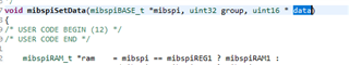
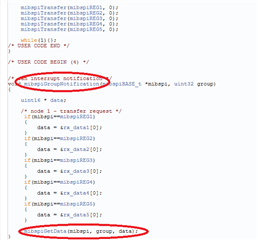
We also modified mibspiSetData() and mibspiGetData() to set data for extended buffers and get data from the extended buffers. The same is shown below.

void mibspiSetData(mibspiBASE_t *mibspi, uint32 group, uint16 * data)

{     ...

     uint32 end = (group == 7U) ? (((mibspi->LTGPEND & 0x00007F00U) >> 8U) + 1U) : ((mibspi->TGCTRL[group+1U] >> 8U) & 0xFFU);
     ...

}

uint32 mibspiGetData(mibspiBASE_t *mibspi, uint32 group, uint16 * data)
{    ...

    uint32 end = (group == 7U) ? (((mibspi->LTGPEND & 0x00007F00U) >> 8U) + 1U) : ((mibspi->TGCTRL[group+1U] >> 8U) & 0xFFU);
    ...

}

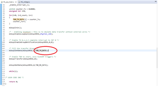
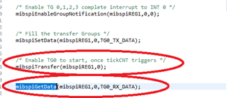
However, I'm still not able to use MIBSPI1 in 256 bytes mode.  Following is the summary of the implementation for transferring 256 bytes of data using MIBSPI1.

After implementing the workaround you suggested, following is the key configurations in my project:

  1. MIBSPI1 Buffers:
    1. MIBSPI1 TG0 buffer: 256
    2. MIBSPI1 TG1 buffer: 0
    3. MIBSPI1 TG2 buffer: 0
    4. MIBSPI1 TG3 buffer: 0
    5. MIBSPI1 TG4 buffer: 0
    6. MIBSPI1 TG5 buffer: 0
    7. MIBSPI1 TG6 buffer: 0
    8. MIBSPI1 TG7 buffer: 0
  2. Added this line to MIBSPIINIT() function: mibspiREG1->MIBSPIE = 0xA00;
  3. Updated value to FF instead of 7F in mibspiSetData() and mibspiGetData().

Can you please suggest the workaround to get this thing working?

Best Regards,

H C Trivedi

  • Hi Trivedi,

    I am working on your issue and i will get back to you soon.

    --

    Thanks & Regards,

    Jagadish.

  • Okay. Meanwhile if you need me to share CCS project or HALCOGEN file, please let me know!

    Regards,

    Trivedi

  • Hi Trivedi,

    To use extended buffers in MibSPI1, we can't directly use the HALCoGen generated code and it also requires some additional manual modifications to get it work

    Can you refer below thread, it explains required manual modifications and also contains an example 

    (+) RM57L843: ENABLING 256 BUFFERS/EXTENDED_BUF_ENA Feature OF MIBSPI1 - Arm-based microcontrollers forum - Arm-based microcontrollers - TI E2E support forums

    --

    Thanks & Regards,

    Jagadish.

  • Hello Jagdish,

    I think this resolved my issue up to a good extent. However, yet to achieve what I'm looking for. I'm able to transmit 255 bytes and not the 256 bytes. 

    (+) RM57L843: ENABLING 256 BUFFERS/EXTENDED_BUF_ENA Feature OF MIBSPI1 - Arm-based microcontrollers forum - Arm-based microcontrollers - TI E2E support forums

    I followed the instruction on this page and figured out tx[256] and rx[256] was never updated from my end and hence I was not able to transmit the data higher than a certain size. 

    After implementing all the corrections/changes, I'm able to transmit an array of size 0 to 254 (i.e. 255 bytes in total). The moment I try sending 256 bytes, it gives all 0's to 128-255 elements of an array. Attached is the CCS project for your reference. Could not upload HALCoGen project due to TI E2E forum technical issue.

    TMS570_3_MIBSPI.zip

    Regards,

    Trivedi

  • Hi Trivedi,

    I found the root cause for the problem

    For 256 extended buffer the highlighted end value should be 256 not 128.

    so please change above line as below and test it, also please let me know the status.

    --

    Thanks & Regards,

    Jagadish.

  • Hello Jagdish, This worked and now I'm able to transfer 256 bytes of data.

    There is still one query I'd like to discuss. In the project file I shared in my last reply contains code for MIBSPI loopback. I had also gone through an example provided with the HALCoGen tool. In that example as well, much similar approach is provided. The only difference I could make out was:

    • in mibspiSetData, one code used address of an array while my code passes the entire array at once.
    • in my example, mibspiGetData was written into main() function while in the example code, mibspiGetData is written into mibspiGroupNotification callback. 

    My query here is, what is the difference in these two approaches and what is the execution sequence of the code in both the cases? Can you please help me with this as well?

    BR,

    Trivedi

  • Hi Trivedi,

    in mibspiSetData, one code used address of an array while my code passes the entire array at once.

    Actually your code is also passing address of array only.

    Giving array name(TG0_TX_DATA) or giving address of first element in array(&TG0_TX_DATA[0]) both implies same.

    in both the cases "data" pointer of function "mibspiSetData" will hold the start address of the array(TG0_TX_DATA).

    in my example, mibspiGetData was written into main() function while in the example code, mibspiGetData is written into mibspiGroupNotification callback. 

    I would say the example code method is good way because, in your code after initiating Transfer Group using the function "mibspiTransfer" we are immediately reading data from mibspiGetData function without make sure of transfer complete.

    The above approach might work but it is not a good practice, because we didn't know whether transfer complete or not, and we are not waiting anywhere until entire transfer completion.

    But if we verify example code

    Here we are reading data only after we are receiving transfer group interrupt only, that means after entire transfer group data transmission and reception completed only, so it is a good approach. And that too it is interrupt mode right so processor can execute other peripheral functions without waiting for transfer complete.

    --

    Thanks & Regards,

    Jagadish.