This thread has been locked.

If you have a related question, please click the "Ask a related question" button in the top right corner. The newly created question will be automatically linked to this question.

TMS570LS0432: PLL under cycle slip causes CAN communication failure

Part Number: TMS570LS0432
Other Parts Discussed in Thread: HALCOGEN

Hi BU experts, 

My customer found 7 pcs TMS570LS0432-based board have no CAN output under low temperature (-40 °C). They did low temperature test on the failure board and I supported them on-site.

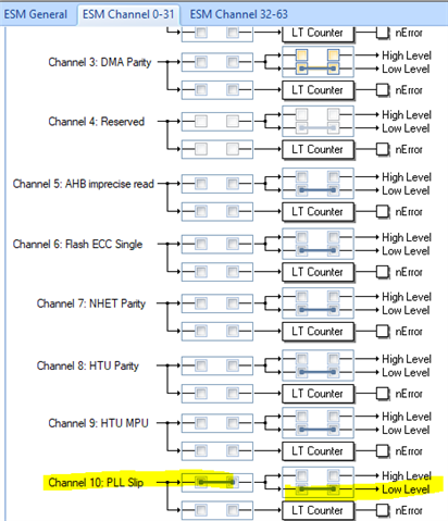
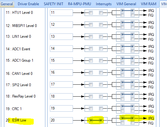
Under -40 °C ambient temperature, configured the CAN working in External Loopback mode and monitored the CAN TX line. We found that actually there are data in TX line but the baud rate is not right (only 125 kbps but the expected is 500 kbps). This phenomenon indicates that the clock of CAN controller is not right. So we checked the crystal oscillator and the PLL status. The crystal oscillator is fine, but we found that GLBSTAT.RFSLIP bit is set which means that "A PLL under cycle slip has been detected". 

My customer wants to know: 

1). why "PLL under cycle slip" is happened and what is the probability of this phenomenon? 

2). It seems that this failure is related to temperature and is a transient failure, does Errata Note include this one? ( I checked Errata notes of Silicon Rev A, I would like to check with you if this failure is similar to SSWF021#45? 

3). Does TI have workaround to detect this failure under normal temperature or low temperature? And workarounds to avoid it? 

4). They also want to do Failure Analysis, do we support do this low temperature FA? 

Thanks. This failure has caused a relatively serious impact on the customer side, please help check this asap. 

BR, 

Will 

  • Hi Will,

    The probability of getting PLL slip is higher at low temperature. By default the PLL clock is configured by to automatically switch-over to the oscillator and the ESM/exception is generated in case of a PLL slip. In the exception service routine, you can disable then re-enable the PLL to lock the PLL.

    A PLL slip may be configured to generate a system reset. Does the PLL get recovered after reset?

  • You can follow this procedure to disable and reenable the PLL in the exception service routine:

    1. Switch all clock domains from PLL1 to the oscillator
    2. Disable PLL1 with CSDISSET. This action disables the PLL and causes the slip signal to no longer be driven.
    3. Clear the RFSLIP or FBSLIP status flags in GLBSTAT
    4. Re-enable PLL1 with CSDISCLR.
    5. Switch the clock domains back to PLL1.

    To generate interrupt when PLL1 Slip occurs:

    1. Make sure the BPOS=0x1, ROS=0 (PLLCTL1 register): OSC will be used after PLL slip, reset is not generated, but ESM flag is set (ESM 1.10 and ESM 1.42)

    2. Enable ESM interrupt 

    The ESM supports up to 128 channels which is divided into 3 groups. The Group 1 has 64 channels: channel 0 to channel 63. By default, the interrupt for channels in Group 1 is not enabled. To enable the interrupt for channel 10 and channel 42 of group 1 (ESM 1.10, ESM 1.42):

    1. esmREG->IESR1 |= 0x1 << 10;  //ESM 1.10

        esmREG->IESR4 |= 0x1 << 10; //ESM 1.42   

        esmREG->ILSR1 &= ~(0x1 << 10); //Low level for ESM 1.10

        esmREG->ILSR4 &= ~(0x1 << 10); //Low level ESM interrupt for ESM 1.42

        You can do this step using HALCoGen:


    2. Enable ESM interrupt in VIM module:

    void esmLowInterrupt(void) will be generated in esm.c

    3. Add code to esmGroup1Notification(..):

    you can write your own code to disable PLL and re-enabled PLL. 

    you can also call the functions generated by HALCOGen

    a. _errata_SSWF021_45_pll1(...)

    b. setupPLL();

    c.  mapClocks();


  • Hi QJ, 

    Thanks so much for your instruction. But in the failure board, even power-on reset can not save the device from the PLL under cycle slip. Not sure whether POR has similar effect as "disable and reenable the PLL " process ? If these two method are different, I will let them try the "disable and reenable the PLL " process. 

    I also suggest customer that let the system work under low-frequency (20 MHz) operating condition, but they said that the whole system application may encounter with serious abnormal functions. 

    What else workarounds can be used? Thanks. 

    Best Regards, 

    Will 

  • whether POR has similar effect as "disable and reenable the PLL " process ?

    If they use the startup function generated by HALCOGen, the PLL slip workaround is called after power-on reset.

    if (_errata_SSWF021_45_both_plls(PLL_RETRIES) != 0U)

    The PLL_RETRIES is 5 by default. You can increase this number to try.