This thread has been locked.

If you have a related question, please click the "Ask a related question" button in the top right corner. The newly created question will be automatically linked to this question.

AM2431: MCU_OSC0_Xn Requirements in Bypass Mode for External CMOS Clock Input

Part Number: AM2431
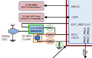
Other Parts Discussed in Thread: CDCLVC1310

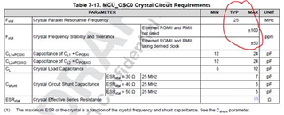
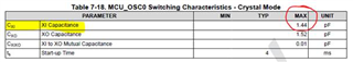
The MCU_OSC0_Xn input has required parameters when using a crystal. (Table 7-17 and Table 7-18)
But we don't specify requirements for an LVCMOS input.

CTRLMMR_MCU_HFOSC0_CTRL (TRM) can be set so we bypass the crystal circuitry.
This allows us to use the LVCMOS digital signal for our clock.

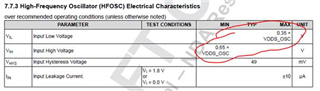
But the section around Figure 7-21 (datasheet) only mentions we need a "1.8V LVCMOS clock source"
What are the requirements?

Frequency: xxMHz ± yy[ppm] what is the required frequency and max variation allowed?
Voltage: V_IH = xx // V_IL = yy what are the max/min input voltage ranges we need to care about in bypass mode?
Duty Cycle: what is the duty cycle requirement of the clock source?
Jitter: what is the jitter requirement (rms or pk-pk) of the clock source?
CLwhat is the input capacitance of MCU_OSC0_XI pin in bypass mode?
Tr/Tf: what are the rise/fall time requirements for the clock?

etc...

Can we provide these requirements please?

  • Hello Darren,

    When providing an LVCMOS clock source for MCU_OSC0_XI and tying MCU_OSC0_XO to ground, the High-Frequency Oscillator is operating in "Overdrive" mode. The device clocking requirements remain the same whether using Crystal/Active Mode or LVCMOS/Bypass mode. 25MHz is a hard requirement as this signal is used as source to derive the internal MCU_PLL0 clock and other critical downstream clock signals.

    • Frequency: Typ: 25 MHz NOTE: 25 MHz is required for device to function.
    • Vil/Vih Voltage: (In Datasheet)
    • Duty Cycle: Min: 45%, Typ: 50%, Max: 55%
    • Crystal Load Capacitance: Min: 6 pF; Max: 12pF
    • XTAL_XI Input Capacitance: (In Datasheet)
    • Maximum rise/fall time (10->90% & 90->10%) = 8nS

    We will add any missing Oscillator parameters for the next datasheet release.

    I hope this helps clear up some confusion. Please refer to the TMDS243GPEVM Evaluation board which implements the CDCLVC1310 Clock IC and provides a resistor network for switching between the 25 MHz crystal signal and the 25 MHz CDCLVC1310 signal.

    Best Regards,

    Zackary Fleenor

  • Hi Zackary,

    I appreciate your comments and will watch for the datasheet update.

    Thanks!

    Regards,
    Darren

  • We do not define output clock jitter, so please ignore the value Zach provided above.

    The load capacitance values Zach provided defines the valid crystal circuit load supported by the oscillator, which is unrelated to the LVCMOS use case.

    Regards,
    Paul

  • Hi Paul,

    I understood the capacitance from Table 7-18 Zach shared was for the Crystal input (non-bypass mode) - so I ignored here.

    But the comment about the min/max input capacitance for XI-pin in "bypass" mode being 6pF~12pF was around what I expected.
    Do I understand this 6pF~12pF min/max is the XI input capacitance in "bypass" mode to use an external LVCMOS clock source?

    Regards,
    Darren

  • No. The capacitance range of 6pF to 12 pF defines the capacitance load range of the crystal circuit that is supported by the oscillator, which is completely unrelated to the LVCMOS use case. Please refer to the Load Capacitance description in the MCU_OSC0 Internal Oscillator Clock Source section for an explanation of crystal circuit load capacitance.

    The max input capacitance of the XI pin is 1.44pF.

  • Hi Paul,

    Appreciated! That makes more sense...12pF was a little on the high-side.