This thread has been locked.

If you have a related question, please click the "Ask a related question" button in the top right corner. The newly created question will be automatically linked to this question.

TM4C1294KCPDT: When I use the EPI to read data from the adc1175, the chip becomes very hot,but the data is just correct ,is there something wrong in the epi config ?

Part Number: TM4C1294KCPDT
Other Parts Discussed in Thread: ADC1175

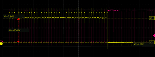
When I use epi0s0-s15 to read data from two adc1175s(8Bit adc), epi0s30 is configured as CS and it connects to the adcclk pin to provide clock to both adcs. I found that maybe  the IO of TM4C1294KCPDT absorbs so much current that the high level of the data signal is only 2.7V (as you can see in the pic below), and the chip becoms very hot, so i just disable the epi0s0-s15, and configure them to gpio input , then it get normal, the high level of the data signal is 3.3V again.

I don't know why it happened,  the data received is correct when i use epi read ,  it's just too hot, may reach 90 degrees Celsius quickly.

those are my code to configure the EPI  as Host-bus 16bit mode:

static inline void ADCInterfaceInit()
{
    //IOfunction is already in Pinout()
    MAP_SysCtlPeripheralEnable(SYSCTL_PERIPH_EPI0);
    while(!SysCtlPeripheralReady(SYSCTL_PERIPH_EPI0));
 
    //EPIDividerSet(EPI0_BASE10);//
    EPIModeSet(EPI0_BASE,EPI_MODE_HB16);
    EPIConfigHB16Set(EPI0_BASE,EPI_HB16_MODE_ADDEMUX|EPI_HB16_CSCFG_CS,0);
    EPIAddressMapSet(EPI0_BASE,EPI_ADDR_PER_BASE_A|EPI_ADDR_PER_SIZE_256B);//set addr map as datasheet's advice,not important, beacuse i just read data from an adc1175.
    while(HWREG(EPI0_BASE + EPI_O_STAT& EPI_STAT_INITSEQ);//wait
}
 here is the signal when the epi read data from adc1175(yellow line is epi0s3,PH3,red line is epi0s30(CS),PN3):
  • Hi,

      EPI I/Os are configured for 8mA drive strength. When you drive 16 I/Os at the same time, it is going to consume quite some current. If you have another MCU, I will suspect you will experience similar situation. It may be slighter better but not much. I don't think your code is wrong since it is already reading the data correctly. The only thing I can think is to try with a lower drive strength. See below in file gpio.c in TivaWare driverlib. Change from 8mA to 4mA and see if the temperature decrease a bit. 

    void
    GPIOPinTypeEPI(uint32_t ui32Port, uint8_t ui8Pins)
    {
    //
    // Check the arguments.
    //
    ASSERT(_GPIOBaseValid(ui32Port));

    //
    // Make the pin(s) be peripheral controlled.
    //
    GPIODirModeSet(ui32Port, ui8Pins, GPIO_DIR_MODE_HW);

    //
    // Set the pad(s) for standard push-pull operation.
    //
    GPIOPadConfigSet(ui32Port, ui8Pins, GPIO_STRENGTH_8MA, GPIO_PIN_TYPE_STD);
    }

  • Hi, Charles,

    Thanks for your suggestion, it dose work after I change the io drive strength to 2mA,and the temperature dropped to about 40 ℃ when i drive 16 IO at the same time, but  I don't think this solution solves the problem fundamentally , because this situation is different from the normal input configuration .

    I will explain my question below:

    The yellow line in this screenshot is the high level signal from adc1175 data pin, which connect to the MCU's PH3 pin:

    and  there are some pulses in it ,  it seems that the input status is related to epi clock or cs  (actually just as you can see in the first pic above , when the CS pin goes low ,the data signal becomes normal with a 3.3V  high level while the high level of the data pin will be only 3.11V when the cs pin is high). 

     In contrast ,if I just configure those pin as  GPIO input mode ,that won't happen,the high level is just  3.3V all the time, this is why I didn't realized I should change the drive strenght. I think input mode is high-z or something passive ,and should not drive , and also ,like you said, when i use another MCU, i  haven't  experience such situation ----- I always think  the sink or source current of IOs should be few since they are configured as INPUT.

    What makes me confused is that I only read data from peripheral ,so I thought that EPI's IO would only be in high - z state in the whole time,like the GPIO input mode, but it seems that EPI will start switching IO to drive output at some time. Is there something I missed from the datasheet ?

    Thank you again for your reply. I just want to figure it out and make it clear,because I think maybe i still using it in a wrong way.

  • In contrast ,if I just configure those pin as  GPIO input mode ,that won't happen,the high level is just  3.3V all the time, this is why I didn't realized I should change the drive strenght. I think input mode is high-z or something passive ,and should not drive , and also ,like you said, when i use another MCU, i  haven't  experience such situation ----- I always think  the sink or source current of IOs should be few since they are configured as INPUT.

    What makes me confused is that I only read data from peripheral ,so I thought that EPI's IO would only be in high - z state in the whole time,like the GPIO input mode, but it seems that EPI will start switching IO to drive output at some time. Is there something I missed from the datasheet ?

    If you look at the code I pasted for GPIOPinTypeEPI() it has the below line. The EPI pins are to be controlled by EPI module directory. In another word, the direction of the pins is controlled by EPI module dynamically. When EPI is writing it will change the pins to output. When EPI is reading it will change the pins to input (high-z). Although you are doing only reading, the I/O buffers are already configured for 8mA buffer strength that will consume more power. 

    GPIODirModeSet(ui32Port, ui8Pins, GPIO_DIR_MODE_HW);

  • Ok, thank you , I've understood what you mean. Maybe fixing the hardware design is a better solution for me Joy