Other Parts Discussed in Thread: TMS570LS2135
Hi Team,
TMS570LS0914 is used for new project, it has a program issue. Could you check it for customer? Thanks.
I also add the attachment for this issue.
TMS570LS0914 Connection failed by CCS8.3.1.docx
Background:
TMS570LS2135 is mass production on customer side, it can work well, it can be programed by CCS6.0.1, it also can debug well.
Now customer want to cost down, so the new project is using TMS570LS0914, the software is same as old project (TMS570LS2135). The flash of TMS570LS0914 is smaller than TMS570LS2135.
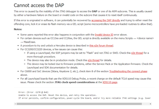
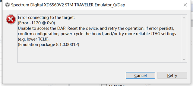
Failure performance:
TMS570LS0914 programing is failed when using CCS8.3.1. It can be debug.
Action for Program:
The program method is same for those two different devices. For the old CCS version, it doesn’t have TMS570LS0914, So customer update the CCS to CCS8.3.1.
1. Create a project
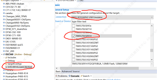
2.Load Gel file
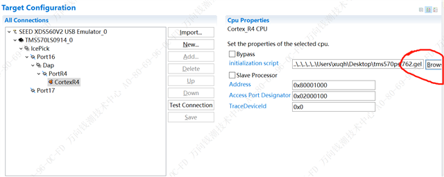
3. Load GEL file_2
4. Load GEL File
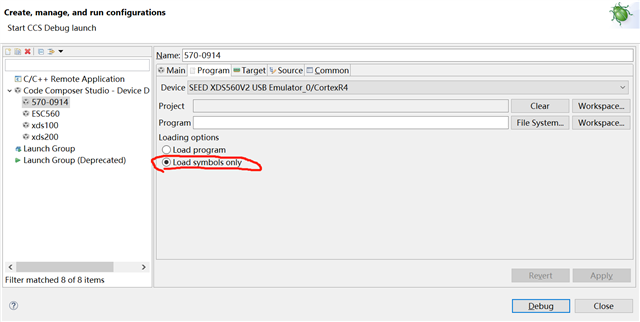
5.Load GEL File_3
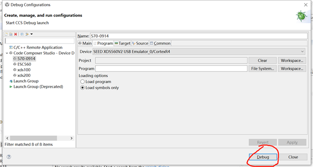
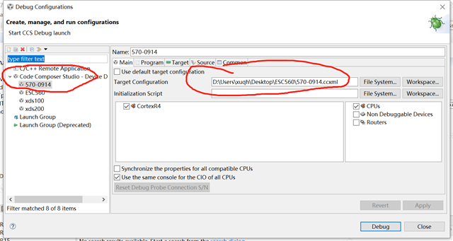
6.Follow action
7.Follow Action
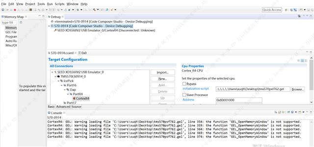
8.Detail test Result
All the log for the program action:
[Start: Spectrum Digital XDS560V2 STM TRAVELER Emulator_0]
Execute the command:
%ccs_base%/common/uscif/dbgjtag -f %boarddatafile% -rv -o -F inform,logfile=yes -S pathlength -S integrity
[Result]
-----[Print the board config pathname(s)]------------------------------------
C:\Users\xuqh\AppData\Local\TEXASI~1\CCS\
ti\0\0\BrdDat\testBoard.dat
-----[Print the reset-command software log-file]-----------------------------
This utility has selected a 560/2xx-class product.
This utility will load the program 'sd560v2u.out'.
The library build date was 'Apr 30 2019'.
The library build time was '11:41:17'.
The library package version is '8.1.0.00012'.
The library component version is '35.35.0.0'.
The controller does not use a programmable FPGA.
The controller has a version number of '6' (0x00000006).
The controller has an insertion length of '0' (0x00000000).
The cable+pod has a version number of '8' (0x00000008).
The cable+pod has a capability number of '7423' (0x00001cff).
This utility will attempt to reset the controller.
This utility has successfully reset the controller.
-----[Print the reset-command hardware log-file]-----------------------------
The scan-path will be reset by toggling the JTAG TRST signal.
The controller is the Nano-TBC VHDL.
The link is a 560-class second-generation-560 cable.
The software is configured for Nano-TBC VHDL features.
The controller will be software reset via its registers.
The controller has a logic ONE on its EMU[0] input pin.
The controller has a logic ONE on its EMU[1] input pin.
The controller will use falling-edge timing on output pins.
The controller cannot control the timing on input pins.
The scan-path link-delay has been set to exactly '2' (0x0002).
The utility logic has not previously detected a power-loss.
The utility logic is not currently detecting a power-loss.
-----[The log-file for the JTAG TCLK output generated from the PLL]----------
Test Size Coord MHz Flag Result Description
~~~~ ~~~~ ~~~~~~~ ~~~~~~~~ ~~~~ ~~~~~~~~~~~ ~~~~~~~~~~~~~~~~~~~
1 none - 01 00 500.0kHz - similar isit internal clock
2 none - 01 09 570.3kHz - similar isit internal clock
3 64 - 01 00 500.0kHz O good value measure path length
4 16 - 01 00 500.0kHz O good value auto step initial
5 16 - 01 0D 601.6kHz O good value auto step delta
6 16 - 01 1C 718.8kHz O good value auto step delta
7 16 - 01 2E 859.4kHz O good value auto step delta
8 16 + 00 02 1.031MHz O good value auto step delta
9 16 + 00 0F 1.234MHz O good value auto step delta
10 16 + 00 1F 1.484MHz O good value auto step delta
11 16 + 00 32 1.781MHz O good value auto step delta
12 16 + 01 04 2.125MHz O good value auto step delta
13 16 + 01 11 2.531MHz O good value auto step delta
14 16 + 01 21 3.031MHz O good value auto step delta
15 16 + 01 34 3.625MHz O good value auto step delta
16 16 + 02 05 4.313MHz O good value auto step delta
17 16 + 02 13 5.188MHz O good value auto step delta
18 16 + 02 23 6.188MHz O good value auto step delta
19 16 + 02 37 7.438MHz O good value auto step delta
20 16 + 03 07 8.875MHz O good value auto step delta
21 16 + 03 15 10.63MHz O good value auto step delta
22 16 + 03 1E 11.75MHz {O} good value auto step delta
23 64 + 02 3E 7.875MHz O good value auto power initial
24 64 + 03 0E 9.750MHz O good value auto power delta
25 64 + 03 16 10.75MHz O good value auto power delta
26 64 + 03 1A 11.25MHz O good value auto power delta
27 64 + 03 1C 11.50MHz O good value auto power delta
28 64 + 03 1D 11.63MHz O good value auto power delta
29 64 + 03 1D 11.63MHz O good value auto power delta
30 64 + 03 13 10.38MHz {O} good value auto margin initial
The first internal/external clock test resuts are:
The expect frequency was 500000Hz.
The actual frequency was 499110Hz.
The delta frequency was 890Hz.
The second internal/external clock test resuts are:
The expect frequency was 570312Hz.
The actual frequency was 569976Hz.
The delta frequency was 336Hz.
In the scan-path tests:
The test length was 2048 bits.
The JTAG IR length was 6 bits.
The JTAG DR length was 1 bits.
The IR/DR scan-path tests used 30 frequencies.
The IR/DR scan-path tests used 500.0kHz as the initial frequency.
The IR/DR scan-path tests used 11.75MHz as the highest frequency.
The IR/DR scan-path tests used 10.38MHz as the final frequency.
-----[Measure the source and frequency of the final JTAG TCLKR input]--------
The frequency of the JTAG TCLKR input is measured as 10.37MHz.
The frequency of the JTAG TCLKR input and TCLKO output signals are similar.
The target system likely uses the TCLKO output from the emulator PLL.
-----[Perform the standard path-length test on the JTAG IR and DR]-----------
This path-length test uses blocks of 64 32-bit words.
The test for the JTAG IR instruction path-length succeeded.
The JTAG IR instruction path-length is 6 bits.
The test for the JTAG DR bypass path-length succeeded.
The JTAG DR bypass path-length is 1 bits.
-----[Perform the Integrity scan-test on the JTAG IR]------------------------
This test will use blocks of 64 32-bit words.
This test will be applied just once.
Do a test using 0xFFFFFFFF.
Scan tests: 1, skipped: 0, failed: 0
Do a test using 0x00000000.
Scan tests: 2, skipped: 0, failed: 0
Do a test using 0xFE03E0E2.
Scan tests: 3, skipped: 0, failed: 0
Do a test using 0x01FC1F1D.
Scan tests: 4, skipped: 0, failed: 0
Do a test using 0x5533CCAA.
Scan tests: 5, skipped: 0, failed: 0
Do a test using 0xAACC3355.
Scan tests: 6, skipped: 0, failed: 0
All of the values were scanned correctly.
The JTAG IR Integrity scan-test has succeeded.
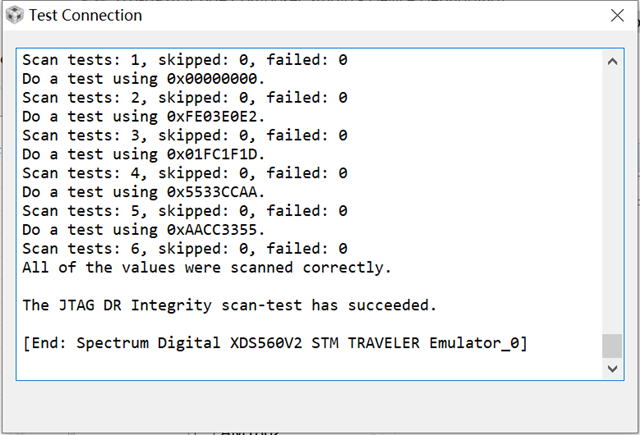
-----[Perform the Integrity scan-test on the JTAG DR]------------------------
This test will use blocks of 64 32-bit words.
This test will be applied just once.
Do a test using 0xFFFFFFFF.
Scan tests: 1, skipped: 0, failed: 0
Do a test using 0x00000000.
Scan tests: 2, skipped: 0, failed: 0
Do a test using 0xFE03E0E2.
Scan tests: 3, skipped: 0, failed: 0
Do a test using 0x01FC1F1D.
Scan tests: 4, skipped: 0, failed: 0
Do a test using 0x5533CCAA.
Scan tests: 5, skipped: 0, failed: 0
Do a test using 0xAACC3355.
Scan tests: 6, skipped: 0, failed: 0
All of the values were scanned correctly.
The JTAG DR Integrity scan-test has succeeded.
[End: Spectrum Digital XDS560V2 STM TRAVELER Emulator_0]
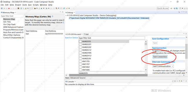
9. Start to connection
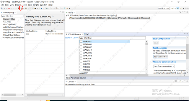
10. Fail screenshot
Best Regards
Songzhen Guo
+86 15505131552