This thread has been locked.

If you have a related question, please click the "Ask a related question" button in the top right corner. The newly created question will be automatically linked to this question.

TM4C129ENCPDT: TM4C129ENCPDT audio over ethernet

Part Number: TM4C129ENCPDT
Other Parts Discussed in Thread: TIDM-TM4C129POEAUDIO, , TPA3111D1, OPA322
For our NVR project we need to make two separate Audio Boxes that will be connected with NVR over ethernet. This Box should be able to provide two way Audiocommunication and also the real time audio should be available to the NVR (Intel ADL-PS processor) over ethernet. 
We have come across the TIDM-TM4C129POEAUDIO reference design that looks suitable for our application. We have some queries regarding this solution that we would like to discuss with you.
  • In the TM4C129ENCPDT datasheet, there is no mention of Internal Audio codec or Mic-In/Speaker-out signals. Please share the detailed pin-mapping and audio codec details.
  • We want to add an 8W speaker out instead of the existing Headphone amplifier. We are planning to use a TPA3111D1 or similar Audio amplifier. Please let us know if it can work in the TIDM-TM4C129POEAUDIO system?
  • We need the realtime Audio data (Audio-In and Audio-out) access at Intel ADL-PS via Ethernet. Does the existing reference design support this?
  • Do we need any specific drivers/firmware on the host side (Intel ADL-PS)? Is the reference design validated on Intel platform with Linux/Windows OS?
We also have a requirement of 2-channel PoE Ethernet bridge IC at NVR side.  There is no native ethernet support at Intel so we need PCIe to Etrhenret bridge controller and also make it PoE enabled (Class-A,15W). Please suggest a solution for this as well. 
We can have a call to discuss this requirement in detail. Let me know your convenient time. 
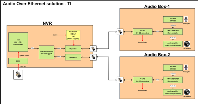
Please check the following block diagram for your reference. We need to achieve this solution.
  • In the TM4C129ENCPDT datasheet, there is no mention of Internal Audio codec or Mic-In/Speaker-out signals. Please share the detailed pin-mapping and audio codec details.

    Hi,

       I'm not familiar with this reference design. There is no native Mic input and Audio output signals as depicted in your diagram to directly interface with OPA322 and TPA3111D1.  Per the user's guide,  the 3rd party Open-Source Opus Audio Codec is used. Please refer to the Audio-Control Block section about how capturing voice and voice playback are implemented also also the reference design schematic.  

    4.3 Audio-Control Block
    As shown in Figure 3, the audio-control block is responsible for initializing the audio interfaces, capturing
    the voice from the microphone, compressing the raw audio data, and decompressing the received audio
    data. The block is also responsible for the playback of the decompressed raw data.
    4.3.1 Initializing the Audio Interface
    The application calls the API AudioInit to initialize the audio interfaces and data paths. The audio interface
    initialization requires the system clock frequency. This frequency generates the 48kHz of sampling and
    playback rate.
    4.3.2 Voice Capture and Compression Path
    The ADC one, sample sequencer two, and ADC channel nine create the voice capture. The ADC zero
    uses the external pin trigger since the timer trigger is already used in the touch-control block. This pin
    triggers by timer 3B with a configuration of a frequency of 48 kHz in pulse width modulation (PWM) mode.
    The pin generates a rising edge trigger to the ADC for sampling.
    A sample and hold of 64 clocks configures the ADC to ensure that the internal capacitor is well-charged
    during the sampling period before the conversion starts. The direct memory access (DMA) channel’s
    configuration is for the ping-pong mode to transfer 20 ms worth of ADC samples. When either the ping or
    pong buffer completes, the opus encoder calls to compress the data.

    4.3.3 Voice Decompression and Playback Path
    The voice playback uses the Timer 0B in PWM mode. The timer uses a PWM period corresponding to 48
    kHz in 16-bit mode.
    The DMA channel enables for the timer in ping-pong mode. When the network receives a compressed
    data packet, it first runs the opus decoder to get the raw PCM data. This data copies to either the ping or
    pong buffer based on which is available. The DMA’s primary or alternate control structure enables so that,
    on the next DMA request, the data transfers to the timer’s match register. Based on the match register
    value, the timer generates a corresponding PWM duty cycle, which is then passed through an external
    filter to reconstruct the audio.

    • We want to add an 8W speaker out instead of the existing Headphone amplifier. We are planning to use a TPA3111D1 or similar Audio amplifier. Please let us know if it can work in the TIDM-TM4C129POEAUDIO system?

    Sorry, I have no knowledge of TPA3111D1. I will suggest you open a new thread specifying TPA3111D1 as the party number so the thread will be automatically routed to the SME. As mentioned before, TM4C129 MCU does not have any native audio in and out capability that interface directly with TPA and OPA.