This thread has been locked.

If you have a related question, please click the "Ask a related question" button in the top right corner. The newly created question will be automatically linked to this question.

MSPM0L1306: VREF+ pin input impedance and ADC measurements

Part Number: MSPM0L1306

Hello,

I'm using the MSPM0L1306TDGS20R with a DC/DC boost converter at 3.3V to supply the device's VDD pin. As is typical with DC/DC converters, it can be a bit noisy. I'm doing ADC conversions on an NTC thermistor and would really like to have 3.3V as the ADC reference, but I think that the noise on this supply is affecting the ADC results. I had the idea to take the 3.3V supply from the boost, RC filter it, and feed it to the VREF+ pin on the MCU. But I don't know what bias current goes into this pin (and how it might vary over time or ADC operation). I'd need this info to choose the R value in my RC filter.

Or maybe doing it this way, i.e., not having an active buffer into the VREF+ pin, is just a bad idea from the start.

Any words of wisdom appreciated.

Thanks, Randy

  • The voltage drop across the resistor should be small enough compared to the voltage across the filter capacitor to maintain the desired voltage at the VREF+ pin.

    You may also consider using an op-amp buffer between the filtered voltage and the VREF+ pin to provide additional isolation and stability.

  • Thanks, Zain. I realize this, but that's why I need to know the input resistance (or input current) of that VREF+ pin.

    Unfortunately, this is a very high volume product where even fractions of a penny matter for the BOM cost, so buffering with an op-amp is not an option.

  • Hi Randy,

    I will be better if you choose the VREF with the 3.3V, even if is just connected to VDD- > I assume this is what you are trying to do.

    But I don't know what bias current goes into this pin (and how it might vary over time or ADC operation). I'd need this info to choose the R value in my RC filter.

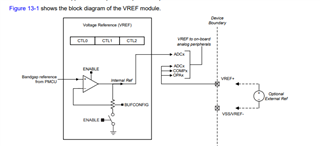
    I don't think there will be a high inuput bias current, due to the VREF+ will be directly used by ADC as the reference, it won't need to driver internal VREF module:

    A decoupling capacitor is better for external reference:

    I do not know what is a proper vaule for 3.3V input, while I suggest you can try with 1uf, and check if it need to increase to get better reference performance. -> This capacitor should be as closed as VREF+ and VREF-/Vss pin.

    While, you can add some RC filter circuit near the boost output. The maximum leak current on the pin is 100nA, maybe you can take this for design reference:

    B.R.

    Sal