This thread has been locked.

If you have a related question, please click the "Ask a related question" button in the top right corner. The newly created question will be automatically linked to this question.

Tm4c1233h6pge how to configure external pull up resistor

Other Parts Discussed in Thread: TM4C1233H6PGE

Hi,

Im using TM4c1233h6PGE for Industrial Automation. i want to have 16 Push button switches connected to port L & G. I have connected external pull up resistor to these input pins. I used the flowing code for configuring it as input pins 

GPIODirModeSet(GPIO_PORTG_BASE,ALL_GPIO_PINS,GPIO_DIR_MODE_IN);
GPIOPadConfigSet(GPIO_PORTG_BASE,ALL_GPIO_PINS,GPIO_STRENGTH_2MA, GPIO_PIN_TYPE_STD);
GPIOIntTypeSet(GPIO_PORTG_BASE, ALL_GPIO_PINS, GPIO_RISING_EDGE);
GPIOPinIntEnable(GPIO_PORTG_BASE,ALL_GPIO_PINS);


//Input Interrupt - PORT L
GPIODirModeSet(GPIO_PORTL_BASE,ALL_GPIO_PINS,GPIO_DIR_MODE_IN);
GPIOPadConfigSet(GPIO_PORTL_BASE,ALL_GPIO_PINS,GPIO_STRENGTH_2MA, GPIO_PIN_TYPE_STD_WPU);
GPIOIntTypeSet(GPIO_PORTL_BASE, ALL_GPIO_PINS, GPIO_RISING_EDGE);
GPIOPinIntEnable(GPIO_PORTL_BASE,ALL_GPIO_PINS);

But with this setup my input pin are not working after prolonged usuage. Its damaging my IC input pin. so i have two questions

1. In software segment, how to configure a input pin with external pull up resistor. 
2. Im using 2MA WPU per pin as per code, which will account to 18MA circuitary per side for high industry application, if the internal pull up resistor is used, which will make input pins not to work. so how to solve the problem. what is concept of sinking current with input  

  • If the pin is set as an input it should not sink current unless your pull-ups are connected to a voltage above the CPU I/O voltage.

    It's not clear to me how you have your pull-ups and switches configured.

    That code also does not look right.  I do not recall there being an ALL_GPIO_PINS definition.

    As far as your inputs failing after time.  Do you have some sort of ESD protection?  Also how are your pushbuttons configured.?


    Robert

  • HI Robert,

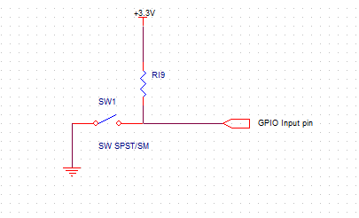
    Pull up resistors are connected with switch and gpio input as shown below.

    ALL_GPIO_PINS is user defined as below

    #define ALL_GPIO_PINS GPIO_PIN_0 | GPIO_PIN_1 |GPIO_PIN_2 | GPIO_PIN_3 | GPIO_PIN_4 | GPIO_PIN_5 | GPIO_PIN_6 | GPIO_PIN_7

    With ESD protection, counter measures are taken with assembly and circuitary also.

    My suspect would be GPIO pins Maximum current rating exceeds the level specified in Recommended GPIO operation for TIVA series. If the internal pull up is used by the system instead of my external pull up, then 8*2MA = 16MA current cosumption which is nearly the maximum operating current condition for tiva. this could make GPIO failure  

  • Hello Arunachalam,

    The maths here is wrong. The current per GPIO is 2 mA and not 8*2mA. If the current is damaging the pad then it would because the current to one particular pad is execssive.

    Secondly, the 2mA rating is minimum current source and sink guaranteed. In actual circuit it would be higher.

    Lastly, what is the external Pull Up resistor strength? That is what is going to decide the actual current. Also there is no debounce cap, which could create excessive slew rate that may cause damage. The C along with the R form a RC circuit to increase the rise and fall rate.

    Regards

    Amit

  • Hi,

    Do you use really 16 input pins? if yes (seems from code) instead I suggest you to arrange them as a keyboard 4x4 - four rows and four columns, which may reside on only a single port. 

    Usually such arrangement needs also some diodes to protect the pins - you may find out on the internet schematics - or even an already made keyboard.

    Take into account the debouncing should be mandatory used.

    Petrei

  • Arunachalam V said:

    Pull up resistors are connected with switch and gpio input as shown below.

    OK, first thought is either turn off the pull up or add a resistor on the input pin, you've nothing to limit the current drawn from the pin.  Personally I'd turn off the internal pull-up, it's of no help to you.  Amit, does TI specify the miniumum resistance/maximum pull-up current that will be supplied by an input pin?  Or a limit on how many pull-ups can be active simultaneously?

    My second is that I do not see any ESD protection.  Presumably you've simplified your schematic?

    I'd also suggest polling rather than interrupt and echo Petrei's suggestion of a scanning arrangement rather than using 16 discrete inputs if you can.


    Robert

  • Hello Robert,

    No. The data sheet only provides for maximum source current for output pin as 25mA. In this case it is necessary that some form or external protection, either through ESD diodes or a simple RC be provided.

    Regards

    Amit

  • Arunachalam V said:
    my input pin are not working after prolonged usuage. Its damaging my IC input pin.

    Some further detail will be helpful, here: 

    a) How do you define, "prolonged usage?"

    b) How do you know the input pin has been damaged?  Is that damage strictly confined to one - or several - keypad input pins, only?  Have you tested the remainder of the MCU - do other gpio/peripherals still function?

    c) What is the length of "signal run" between your switch and the MCU's inputs?  Too long a run will cause dreaded, "antenna effect" which may render your reads unreliable...

    Always helpful to include some small, series resistor with each gpio input.

    Note that the various (driver library, parameter current settings) apply to GPIO Outputs only - not to GPIO inputs!  When the pin is configured as an input - that xmA parameter is (really), "not in play."

    Agree that the classic, 4x4 keypad scan method, offers many benefits. 

    And - old cb1 past developed a trick which eliminates your regular (i.e. endless) "scan" of the keypad - albeit at the cost of 1 GPIO pin.  Simply employ a diode array which "monitors" each/every keypad input.  (i.e. the diodes' cathodes tie to the GPIO input pins)  Should any input then drive to ground - the diode anodes - tied together and wired to a pull-up resistor and the one added gpio input - will cause that added gpio input to transition to ground.  If you "interrupt" upon that added gpio input's negative edge - you free yourself from regular (endless) keypad scanning which has been known to generate RFI/EMI and does "eat" some MCU "time."  (to escape diodes and pull-up R - believe an HC/HCT30 provides an 8 input nand - which works nicely... that from memory - I'm "in the air" have no easy means to review IC spec...)

  • Given Amit's information (thanks Amit) Arunachalam, I would suggest not using the internal pull-ups.  I don't think it is possible to design a safe and working switch input with the internal pull-ups on given that information.

    I probably wouldn't run the switch input directly to the CPU in any case but that's a different issue.

    Robert

  • Amit Ashara said:

    Hello Robert,

    No. The data sheet only provides for maximum source current for output pin as 25mA. In this case it is necessary that some form or external protection, either through ESD diodes or a simple RC be provided.

    Regards

    Amit


    This was bothering me.  I went and checked.  It is specified.

    Pull-up resistor is specified from 13k to 30k, Pull-down resistor specified from 13k to 35k

    So Pull up current from 250uV to 94uV.  Much more reasonable values.

    So I withdraw my earlier comment that it is not possible to design a series resistor to work with an internal pullup.  I'd still just use the external myself.  I would still want at least a series resistor to the switch as part of the protection.


    Robert

  • Hi GURU,

    Thanks a lot. Here are the details for your question. 

    I used a switch instead of push button. so if i keep all the 8 switch on, the microcontroller is randonly loosing any one or two pins in PORT G(which i configured as input). But still device is working fine. 

    How would i say my microcontroller to use external PULL UP resistor in code ?

    The track from switch to microcontroller is pretty large, no physical track. we are using wire. Wire length will be around 2 meter 

  • Hello Arunachalam

    Even though post is not referred to me: You do not need to tell the uC that there is an external Pull Up.

    Hello Robert,

    The weak internal Pull Up would be OK, but unless there is noise it may not be able to counteract due to the weak nature of the Pull Up. Some form of glitch filter must be placed on the pad, to distingush a key press v/s a noise.

    Regards

    Amit

  • Hi Amit Ashara,

    First let me explain my circuit.

    1. The length of wire from switch to GPIO is 2 meter wire. Its not a track in PCB
    2. Im using External pull up resistor circuit, with resistor value 1k. Im using 16 of such thing to my GPIO configured in port G and port L.
    3. Now my code activates my internal GPIO weak pull up resistor and there is an external circuit also placed

    I have the following Question.

    • How is debounce in switch circuit is going to help me ? 
    • If internal pull up resistor is used, the current flows through each pin to the switch will be around 8MA which is provided from the circuit. so for PORTG, then its 8pins equals to 8*8MA, which is high current application since its sourcing the current  for internal pull up.
  • Hello Arunachalam

    1. The point here is not to use the external Pull but only the internal Pull Up. This Internal Pull Up is a weak circuit. To avoid glitches during key press and release an external cap would be required. The same cap will be used to suppress a noise from the surrounding switches (as you have 2m wires running).

    2. The Current carrying capacity of a Pin is specific to the Pin only. The Port-G is a digital logic after the Pin and it will sense only a High and Low level. The current will be sinked by the Pin/Pad so multiplying by 8 is not a valid current equation.

    3. With a 1K resistor outside if you do the math it is 3.3V/1K = 3.3mA and not 8mA. The 2/4/8mA is the minimum value and not the maximum value of current source and sink. It is guaranteed to source/sink that much current. Anything above it will be decided by how much current (upto 25mA).

    4. When the Port Pins stop responding, does a power cycle of the device get the pins working again. If no, then we need to understand why? If yes, then the external switch is generating voltage ramp rates that are too high and cause the ESD protection of the Pin/Pad to kick in.

    Regards

    Amit

  • Hi Amit,

    The pins are permenantly not working. 

  • Hello Arunchalam,

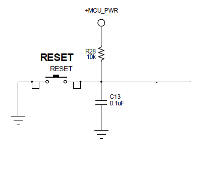
    I would suspect the existing R and switch connector would be the issue. I would suggest something like the image attached before any new GPIO's are damaged.

    Regards

    Amit

  • Arunachalam V said:

    How would i say my microcontroller to use external PULL UP resistor in code ?

    There is nothing in the code to enable/disable or otherwise deal with an external pull-up.  You just treat the input as an input.

    Arunachalam V said:

    The track from switch to microcontroller is pretty large, no physical track. we are using wire. Wire length will be around 2 meter 

    Good heavens.  I would under no circumstances connect that directly to the CPU pin.  I would absolutely want to have conditioning circuitry on that before it reached the micro.

    Robert

  • Amit Ashara said:
    The weak internal Pull Up would be OK, but unless there is noise it may not be able to counteract due to the weak nature of the Pull Up.

    I was concerned about the earlier statement that there was no specified maximum current on the pull-up.  I did not expect the internal pull-up to be that strong which is why I went looking.  I'm not surprised the internal pull-up is not strong enough to be sufficient for a switch.  I am a little surprised the OP has it turned on and fixed on it as a problem.

    Amit Ashara said:
    Some form of glitch filter must be placed on the pad, to distingush a key press v/s a noise.

    There needs to be a filter, it does not need to be external. A high frequency filter in conjuction with a Schmitt would be an ideal frontend with debounce filtering in the SW.

    Robert

  • Hello Robert,

    I agree, that a high frequency filter is required anyways considering the application.

    Regards

    Amit

  • Amit Ashara said:
    . The 2/4/8mA is the minimum value and not the maximum value of current source and sink. It is guaranteed to source/sink that much current. Anything above it will be decided by how much current (upto 25mA).


    This is an output drive spec and since the OP is using the pins as input I think we need to stop referring to it.  It is only confusing things.


    Robert

  • Amit Ashara said:

    Hello Arunchalam,

    I would suspect the existing R and switch connector would be the issue. I would suggest something like the image attached before any new GPIO's are damaged.

    Regards

    Amit


    I would add protection to this (I would in any case but with a 2m cable it's even more of a requirement).  At the very least a series resistor but I think it should also have voltage clamps.

    On a more esoteric point Arunchalam you really should take a look at the rating of your switches and see if they require a minimum current to ensure a long switching life or to guarantee operation.  In some cases you will also find minimum voltage limits. You should find maximum current and voltage switching capabilities documented at least.

    The capacitor in Amit's circuit will actually help to provide a peak turn on current. 

    Robert 

  • To Amit's nice schematic of 03:43 I'd suggest the addition of a 100 ohm R in series with each/every - switch driven - gpio input path.

    If you're "really" driving 16 signals - thru 2 meters - is that not "begging" for trouble?  When we encounter such a situation - we often attempt to employ a reduced cost-low pin count MCU (Cortex M0 anyone?) located close to those switch-signal (common) origins.  That 2nd MCU "avoids" much of the earlier described, "antenna effect" and may "squawk  back" to the main MCU (2 meters distant) via more robust I2C, UART or SPI.

    Talk continues re: parameter 2mA, 4mA, 8mA - to my mind this is all for naught - those settings only come into play when that specific gpio is configured as an output. [edit: note that I first caught this (12:52 yesterday) - now Rob't arrives - but may well bear the repetition!]

    The repeated mis-calculation (by poster) of current drawn points to more study - less, "trial by fire."  (i.e. kill another MCU)

  • HI Guys,


    First of all thank you very much for your replies. So kind of you guys. 

    I think we are not sailing in same boat. Kindly correct me if im wrong.

    The internal pull up resistor uses MCU power, which is 3.3volt if im using WPU in code. So in configration we can specify 2/4/8MA so that, the current rating used by switches is same as specified. Then why do guys say, these rating are only for output pin configuration


  • Hello Arunachalam.

    The current driver is for output pin configuration and not input pin configuration. Please look at the electrical section of the data sheet for "Recommended GPIO Pad Operating Conditions".

    Regards

    Amit

  • Arunachalam V said:
    I think we are not sailing in same boat.

    Bingo!  Not only are we, "Not sailing in the same boat" - we're not in the same ocean!

    If you use external pull-up Rs only - there is nominal (almost zero) current flow - through the MCU's input pin. The current path may be thought of as from 3V3 - thru the pull-up R and onto the (closed) external switch and finally to ground.  Thus - the endless recital (8 mentions now - but who's counting) of gpio's 2,4,8 mA flow is inconsequential - is it not? 

    When the gpio pin is configured as an input - that pin is NOT provisioned to sink nor to source current!  You'd do well to (finally) accept that counsel.  (continued beating of an already dead horse fails to excite/motivate your forum servants)

    Your MCU "killer" mechanism remains unresolved & should rise in your priorities.  My 2nd MCU suggestion presented one cure - you may consider shielding or shortening the 6 foot long antennae/wire - that length most likely visiting havoc upon your (departed, now) MCUs.

    It would prove useful to (temporarily) replace those 6 foot leads with 6" ones - and test to see if damage continues and at about the same rate/frequency.  If so - then you likely have some (unidentified/undiscovered) over-voltage condition impacting your MCU.  On the other hand - should "lead shortening cure" the issue - you may consider using "shielded cable" to carry those long signals or even this vendor's, multi-channel, digital filters.  (includes a series R and bypass C - each/every channel...  (we employ those to reduce EMI/RFI - but they work well as input noise/transient reducers, too.)

    One hopes the (2,4,8 mA) current wale may cease as your boat enters safe (i.e. an inlet (input) harbor....)

  • There are also ICs that manage switch inputs.  Usually marketed as for automotive or PLC use they take care of details like wetting current and the ones I've looked at in detail scan the inputs to reduce current draw and provide an SPI interface.

    Robert

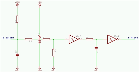
  • I went looking to see if I could find an elementary switch input but couldn't so I made an attempt of my own.  This is not complete and does not cover all situations.  For instance it doesn't provide anything for EMC.

    R3 is sized to provide sufficient wetting current for the switches without being so high as to cause welding.  You also want a current high enough to provide some noise immunity.

    C2 is optional.  It does provide an extra current surge on switch close as wetting, allowing reduction of the current while the switch is closed.  As a filter it's of limited use since it is asymmetric slowing the rise in voltage as the chip opens but any reduction on noise fed into the input will depend on the source impedance. Also closing the switch will only limit the fall speed by the impedance of the switch, capacitor and wiring.  If the capacitor is too large you will weld the switch.

    The pullup supply is 15V for several reasons.  To provide a sufficient voltage for the switch (some switches will fail at low voltages) and to provide a certain level of noise immunity.

    R4 and D2 form a protective circuit. Voltage at R4/R2 a diode drop above VPP will be shunted to VPP and voltage a diode drop below GND will be shorted to GND.  R4 limits the current.  You can use a zener in place of the series diode.  This will protect against some over/under voltage conditions and can be sized to handle mistaken connection to input power.  One downside to using series diodes like D2 is that it provides an alternate way of powering the device.

    R4,R2 and R5 form a divider with R3 to bring the pullup down to logic levels.

    U1.A, U1.B, R1 and C1 is a conditioning circuit.  The initial schmitt trigger inverter squares up the input and provides current for the RC filter.  The RC filter is sized to reduce high frequency noise.  Note that you must keep R large enough to avoid having the output of U1.A  limiting the current.  U1.B then re-squares the signal and inverts it again to match the polarity of the input. The inverters also act as a final protective device.  The hope is that a damaging input will destroy the inverter and prevent the signal from propagating to the CPU allowing repair and/or identification of the original source of the problem rather than leaving a smoking hole where your CPU used to be.

    Robert

  • Hi Robert Adsett,


    I had a look at this link, http://www.digikey.com/en/articles/techzone/2012/apr/protecting-inputs-in-digital-electronics

    So with my system i dont have ESD protection, no input protection at all.

    If im planning to have input protection with RC circuit, what would be my resistor and capacitor value for 3.3v circuit(TM4c1233h6pge) ?. My schematics is below  

    Low pass filter protection for an input

  • The RC will provide little ESD protection, It will provide a noise filter and filter out transition effects.

    EDN has a short intrduction to ESD testing

    http://www.edn.com/design/test-and-measurement/4368466/nderstanding-and-comparing-the-differences-in-ESD-testing

    If you are serious about it you really need to get the standard and see the test details.  This gives you a pretty good idea of what you need to design for.

    You can get some protection with a TVS and a resistor to reduce the peak your diodes would see.  Fig.11 of your Digikey reference does similar with dual Schottky diodes.

    You can get devices that are designed to provide ESD protection.  I'd start there rather than build your own.  You should be able to find some with good application notes.


    Robert