This thread has been locked.

If you have a related question, please click the "Ask a related question" button in the top right corner. The newly created question will be automatically linked to this question.

Audio Communication With Power Over Ethernet project on EK-TM4C129EXL

Other Parts Discussed in Thread: UNIFLASH, LMFLASHPROGRAMMER, TM4C1294NCPDT

Hi all,

There is a TIDM-TM4C129POEAUDIO (Audio Communication with Power Over Ethernet) project made by Amit Ashara. Please use the link to get more details. The thread has been created for those who want to build this project on EK-TM4C129EXL LaunchPad. So lets get started. 

It requires the following HW:

1. EK-TM4C129EXL LaunchPad - available to buy

2. Kentec QVGA Display BoosterPack - available to buy

3. Audio Board - available only design files like schematics, gerber files and BOM. You can find them on the main page of the project

SW:

You can find the SW requirements in the user user guide (unit 6, page 23). Just make sure to follow Test Setup procedure (unit 7, page 24) to compile the project.

Unfortunately, the SW is not going to work right away from the box due to the difference in BoosterPacks pinout between EK-TM4C129EXL LaunchPad and TIDM-TM4C129POE. You can check pinout difference here (unit 4.1, page 7). So fortunately SW can be modified to address that.

1. My first problem was a touch screen - it did not work. To fix that I changed one line of code:

/poe_voice_call_demo/appdrivers/touch.c, line 96

//#define TS_YN_PIN               GPIO_PIN_0//D
#define TS_YN_PIN               GPIO_PIN_6//D

It should be enough to get the touchscreen worked.

2. The screen actually turned black when I powered up the board after loading the FW. 

This is quite strange and your first impression might be like the project is not working but do not worry. I think it happens because by default the brightness is set up for 25% which definitely is not enough to display the graphics. So you want to change the default value:

/poe_voice_call_demo/poe_voice_call_demo.c, line 1583

//
// if no previous setting was found then set it for 25% duty cycle
//
//BrightnessInit(ui32SysClock, 25);
BrightnessInit(ui32SysClock, 75);

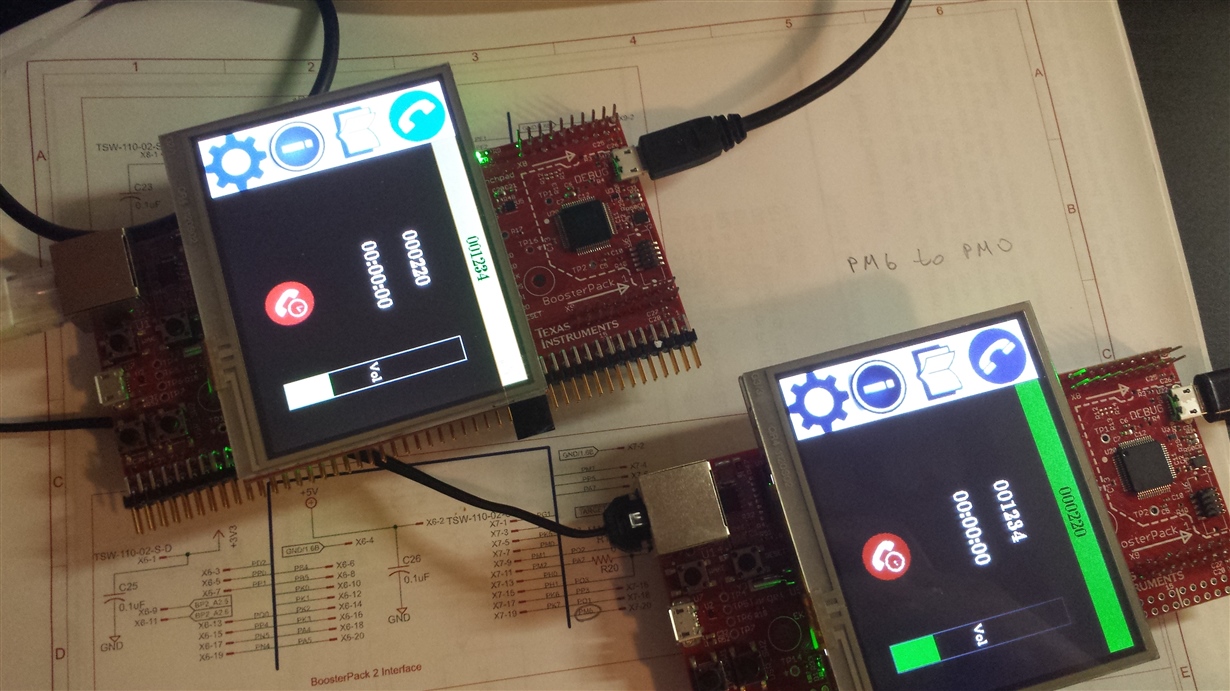
3.  When the call from one board to another one is accepted - they freeze. Counters on both boards stay 0 and the touchscreens are not responding. I think it happens due to the lack of the Audio boards which I will get in a few days. So it looks like that (see picture). So and after only re-cycling the power helps to get the boards recovered.


So it is where I am now and hope Amit can help us and share his knowledge and experience to get it worked.

Thank you again Amit for the great project.

to be continued...

Cheers,

Stan


  • Hello Stan

    I agree with #1. However for #2 that should not be the case. At 25% DC th screen should be viewable

    As for #3, the screen should be still responsive even if the counters do not show any change. Did you connect a debugger and see where the CPU is executing?
  • Hi Amit,

    Amit Ashara said:
    At 25% DC th screen should be viewable

    In terms of the #2, the way I figured out that nothing was wrong with SW and boards is following:

    I load the FW directly from CCS during the Debug mode on the first board. Right after I launched the project nothing happened on the LCD. Then I paused the debugger to see what was going on but the display got viewable. It stayed normal even after disconnecting the debugger.  Then I was able to adjust brightness manually and the board kept that level. The second board was programmed with UniFlash.  After powering up the board the screen was always black. However, at that time I knew the reason and that nothing was wrong with the board. So I pressed bottom left corner and tap somewhere on top to adjust the brightness  - it worked. After saving the settings never got the issue again. The problem with the second approach is you have to make sure your touchscreen works, otherwise no way. So that is why I recommended to change the brightness default value.

    Amit Ashara said:
    As for #3, the screen should be still responsive even if the counters do not show any change.

    Hm, interesting. I really hoped that was just the lack of the audio boards. Anyways, I will check it under the Debug mode.

    Cheers,

    Stan

  • Hello Stan

    Did you try changing the LCD booster pack between the boards?
  • When I was exercising the touch and the brightness problems I did not swap them around because the behavior was the same. I've just tried it now and one board does not freeze. I can terminate the call and the counter is alive. The strange thing is one board works and the other is not and after powering up they can switch.

    Cheers,
    Stan
  • Hello Stan

    Could it be a problem of the LCD Panel? I would suggest debugging the code execution on the failing board.
  • But at any given time the failing board can be different.
  • Another problem is I accidentally wrote the same NODE number to both boards. So and now I cannot re-write it. The way I setup the different NODE now is I have unblocked it in UniFlash and under Debug mode I change it manually in Memory Browser. However, after re-cycling the power it shows the old number. Is it any way to change it?

    Cheers,
    Stan
  • Hello Stan,

    First make sure that you note down the MAC address of the board. Once done, run the JTAG Unlock Sequence to erase all device content and restore the device to factory condition. Then re-program the MAC address using LMFlashProgrammer (do not forget to set the commit control check box). At this point the board is as good as new.
  • Thanks Amit, I was able to rewrite the NODE number quite easily. The only thing I would like to add here is the reference on Application Report: Using TM4C12x Devices Over JTAG Interface where this procedure is well documented (5.3.1 Unlock Sequence using LMFlashProgrammer , page 21).

    Cheers,

    Stan

  • Hello Stan

    The TI Design was released before the application note. However we will add the same to the Design Guide (Thanks)
  • So after programming proper NODE numbers the problem looks as follows:

    There are two boards: A - 001234, B - 004321. Both work fine at the start. Lets say A calls B. When call is accepted, A immediately freezes but B works fine.  And vise versa, when B calls A, B freezes but A goes well.

    So to summarize it - calling party is always stuck when call is accepted, however called party stay healthy. 

    I made a short video to show the problem:

    Cheers,

    Stan

  • Under the Debug mode calling party goes to abort function, line 127 in exit.c right after the call is accepted.

    Cheers,

    Stan

  • Hello Stan

    That is strange. I saw a similar problem during development but that was due to insufficient heap size. I hope the project linker setting has not been modified when you imported the project. Can you please paste a snapshot of the Stack and Heap Size.

    What I can try tomorrow is to run the binary files on my PoE board without the Audio board. That should tell us if the issue is due to lack of Audio board (though I highly doubt)
  • Hi Amit,

    I found what causes that problem. When I was debugging the touch I turned the optimization off. That was the only change I made in the project settings. I have returned it back and now both boards operate fine. 

    However, I need to keep the optimization off. I am going to use this project as a starting point for my own application that obviously involves debugging. So any ideas why optimization settings interfere with board performance and how to avoid it?

    Cheers,

    Stan


  • Hello Stan

    Optimizations affect a lot of things in a code. Since I am not a compiler expert, I would suggest checking with the TI C/C++ compiler forum.
  • Thanks Amit, I will. Just wondering did you debug the project with optimization on?

    Cheers,
    Stan
  • Hello Stan,

    No, I did not. As I mentioned earlier, during development I had to increase heap size to get around the issue. Memory management was tough.
  • Looking in the memory map I must say it is dangerously full especially SRAM:

    With only 520 B left in SRAM the project is not expandable and cannot be used as a starting platform for any user's applications. It should be taken into account that optimization level is already 2.

    So my questions are:

    1. Why the project requires so much heap and stack ( 58% of SRAM )?

    2. Why lwIPlib takes 97kB, seems too much as well ( 38% of SRAM )? What is so special in there?
    3. Is the any way to reduce the usage of SRAM?

    It is a great project, no doubts but without extra room for user's application it is not too much you can do with this.

    Cheers,

    Stan

  • Hello Stan,

    It is the codec that require a lot of SRAM for data buffer allocation during processing of both the encoder and decoder. The space is reserved in heap for the same. There is some work I know of on a lower memory footprint version of the same.
  • Hi Amit,

    That is promising. The application I am interested in OPUS is not required. The near-end part will receive/send frames to/from SPI. Compression is u-law or G711. The Frame size is 80 samples (16bits). Fs=8kHz.

    So with these requirements how much memory is possible to save in comparison to the original project?

    Cheers,
    Stan
  • Hello Stan

    I have not evaluated G7111 on Cortex M4F cores. So I am not sure, but it would good if you can try the same and let us know....
  • Hi Amit,

    Amit Ashara said:
    It is the codec that require a lot of SRAM for data buffer allocation during processing of both the encoder and decoder.

    What if there is just raw data without codec involved. How much memory (approximately) it can save?

    Amit Ashara said:
    The space is reserved in heap for the same. There is some work I know of on a lower memory footprint version of the same.

    Can you tell more about this?

    Cheers,

    Stan

  • Hello Stan

    Almost all of the codec memory can be saved. However the bandwidth consumed on the link will be 8 times (based on the application example) or more than that if higher compression is used. The main concern will be not for a single link but when multiple such units are working at the same time.
  • Stan/Amit,
    Where can I get the software project for this demo that is described above. The TivaWare I have downloaded is
    TivaWare_C_Series-2.1.1.71, and version 156. The display code contains Kentec320x240x16_ssd2119_8bit.c/h not the files that were expected from the download I found, so it results in a couple of functions being warned as implicitly defined. Also errors result in the compilation because there are none of the "opus" files, folders, or items. Can you provide more succinct direction here?
    Thanks,
    Russ
  • Additionally, here are the ARM Compiler flags that came with the project. I have fixed the ones that now start with C:/. You will notice that the "opus" references are the problem references. None of these folders exist in any of the TivaWare adn example installations. Don't know where to get these from...

    -mv7M4 --code_state=16 --float_support=FPv4SPD16 --abi=eabi -me -O2 --include_path="C:/ti/ccsv6/tools/compiler/ti-cgt-arm_5.2.7/include" --include_path="C:/Projects/CCS6Workspace/Royalle III/poe_voice_call_demo" --include_path="C:/Projects/AMI_Fuel_Cel/RoyaleIII_EvalKit/TM4C129POEAUDIO-1.0/" --include_path="C:/ti/TivaWare_C_Series-2.1.1.71/third_party" --include_path="C:/ti/TivaWare_C_Series-2.1.1.71" --include_path="C:/ti/TivaWare_C_Series-2.1.1.71/examples/boards/ek-tm4c1294xl-boostxl-kentec-l35" --include_path="C:/ti/TivaWare_C_Series-2.1.1.71/third_party/lwip-1.4.1/src/include" --include_path="C:/ti/TivaWare_C_Series-2.1.1.71/third_party/lwip-1.4.1/src/include/ipv4" --include_path="C:/ti/TivaWare_C_Series-2.1.1.71/third_party/lwip-1.4.1/ports/tiva-tm4c129/include" --include_path="C:/ti/TivaWare_C_Series-2.1.1.71/third_party/lwip-1.4.1/apps" --include_path="D:/ti/examples/OPUS/opus-1.1.2/include" --include_path="D:/ti/examples/OPUS/opus-1.1.2/silk" --include_path="D:/ti/examples/OPUS/opus-1.1.2/celt" --include_path="D:/ti/examples/OPUS/opus-1.1.2/src" -g --gcc --define=ccs="ccs" --define=PART_TM4C1294NCPDT --define=TARGET_IS_TM4C129_RA1 --define=VAR_ARRAYS --define=FIXED_POINTS --define=OPUS_BUILD --diag_wrap=off --display_error_number --diag_warning=225

  • Russ,

    There is a user guide in the project folder. Just follow through step by step. Amit has done pretty much good job with the documentation. However, make sure to take into account those issues that I have came up with.
  • Hello Russ

    You would need TivaWare 2.1.3.156 for the Serial mode panel driver files. The version of the document is mentioned in the User Guide.